Guide catheter having selected flexural modulus segments

a flexural modulus and segment technology, applied in the direction of flexible pipes, catheters, coatings, etc., can solve the problems of increasing the tendency for back-out again, increasing the back-out frequency, and the device would be very traumatizing to the patient's arteries, so as to increase the rigidity prevent the back-out and increase the flexibility of the guiding catheter

Inactive Publication Date: 2005-02-22
BOSTON SCI SCIMED INC
View PDF37 Cites 168 Cited by
  • Summary
  • Abstract
  • Description
  • Claims
  • Application Information

AI Technical Summary

Benefits of technology

The present invention overcomes the disadvantages associated with the prior art by providing a transition element in the material. The present invention allows for flexibility of a guiding catheter to be increased, while maintaining its ability to prevent guide catheter back-out. The present invention also allows for the rigidity of a guiding cath

Problems solved by technology

One problem that has surfaced is that as more flexible distal sections are placed on these catheters, the incidence of guide catheter back-out is increased.
However, as the flexibility of the distal most section is increased, the tendency for back-out again increases.
However, the resulting device would be very

Method used


Image

  • Guide catheter having selected flexural modulus segments
  • Guide catheter having selected flexural modulus segments
  • Guide catheter having selected flexural modulus segments

Examples


Embodiment Construction

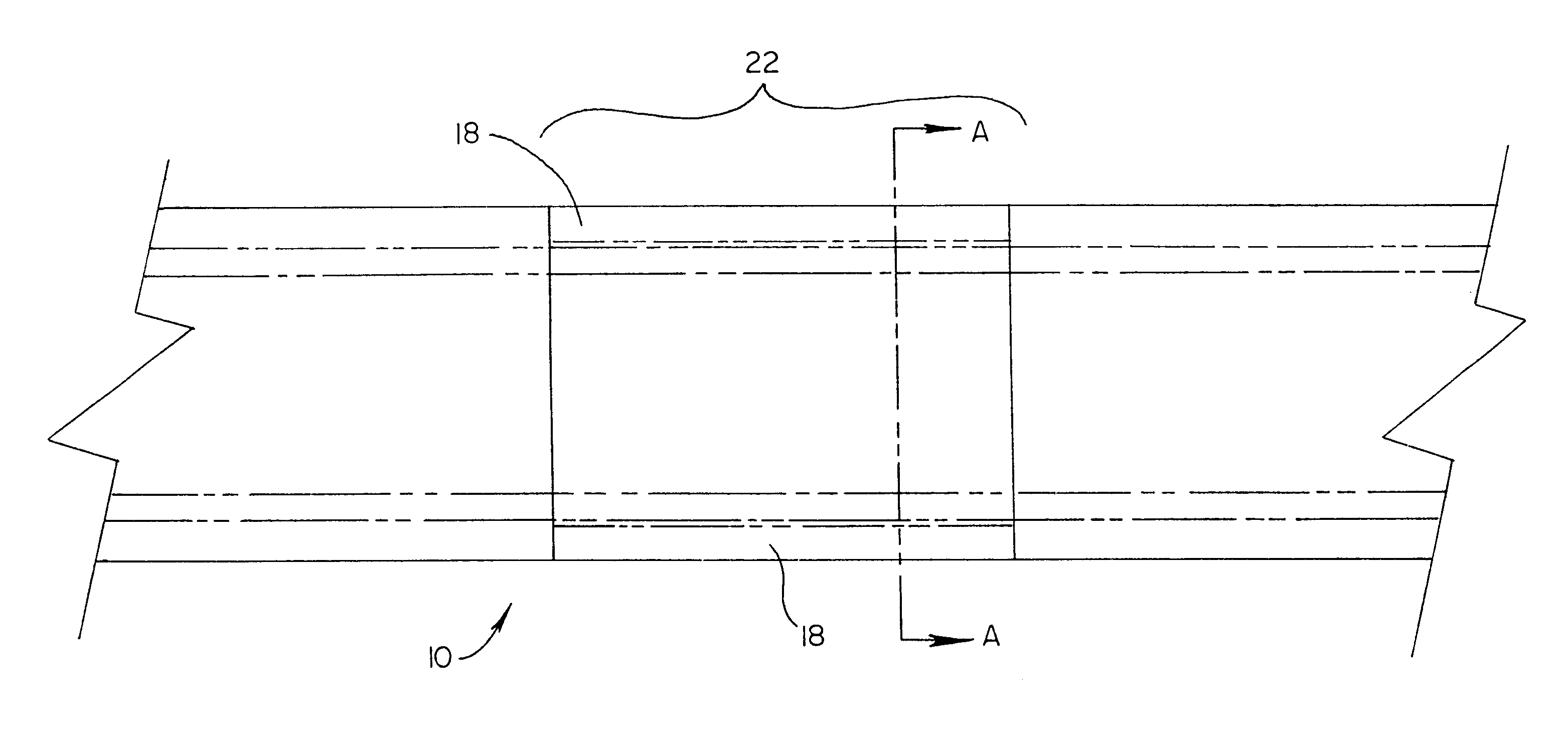
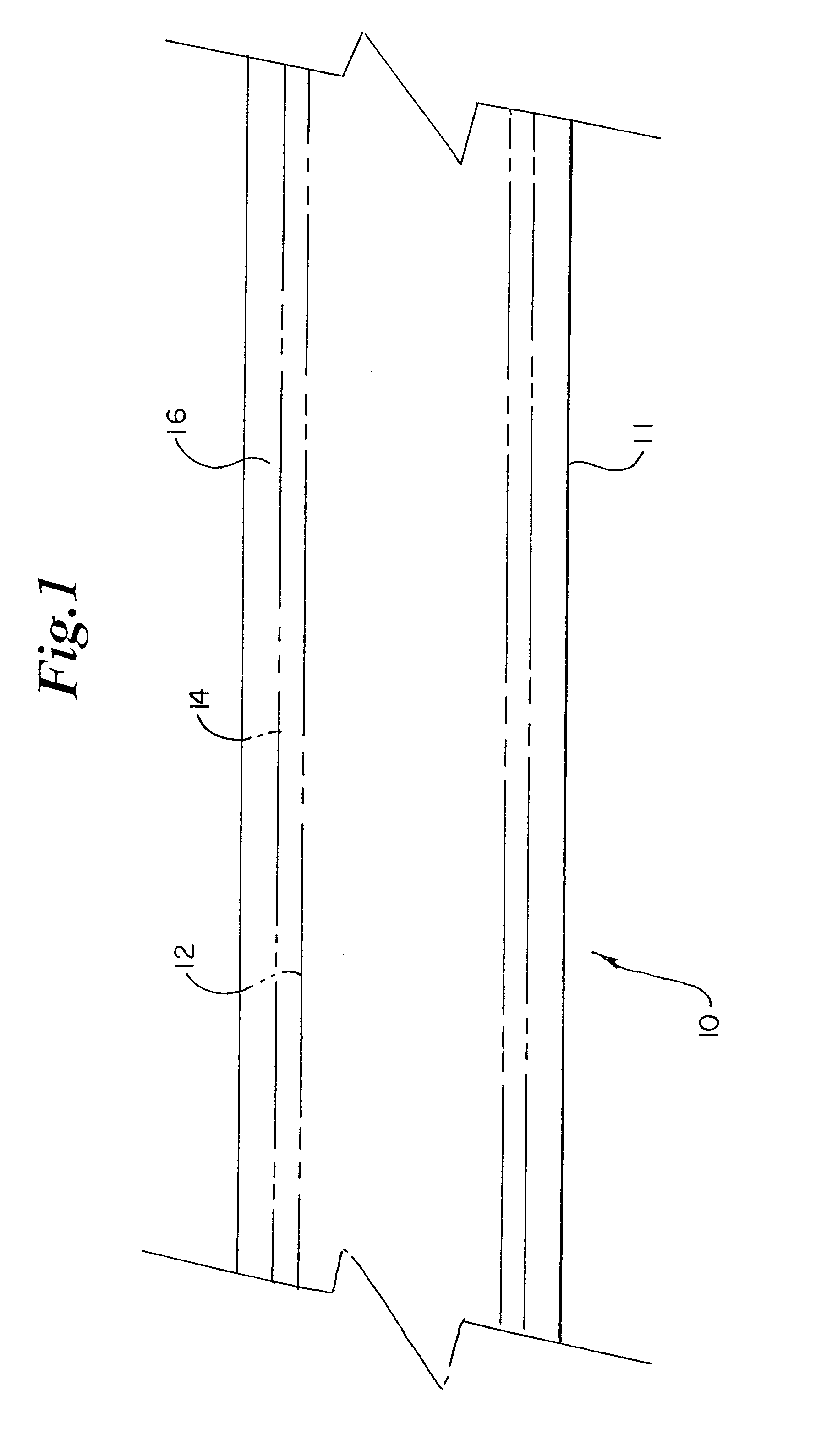
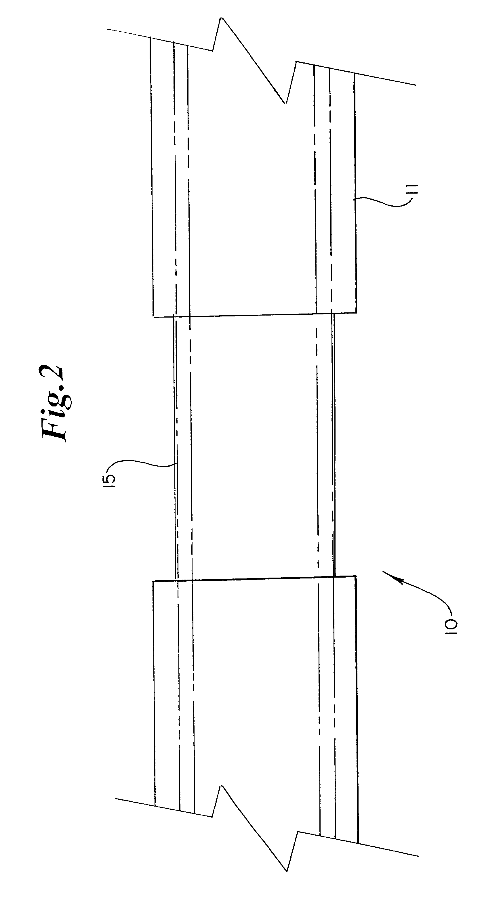
FIG. 1 shows a section of a catheter 10 which is preferably a guiding catheter. Catheter shaft 11 is comprised of an inner tube 12 which is surrounded by a support member 14. Support member 14 is then surrounded by an outer tube 16. Inner tube 12 is represented in FIG. 1 by dashed lines and the support member 14 is represented by a dotted line.

In the preferred embodiment, inner tube 12 is a thin walled PTFE (polytetrafluoroethylene) tube. This creates a smooth, friction-free surface for the passage of other devices through the inner tube. Support member 14 is a 304 stainless steel wire, wound in a braided pattern around inner tube 12. Alternatively, support member 14 could also be comprised of polymer fibers. Outer tube 16 is a polymer jacket which is placed through an extrusion process onto combined layers of inner tube 12 and support member 14. Preferably, outer tube 16 is comprised of PEBAX®, a polyether block amide (PEBA) available from ATOMCHEM POLYMERS, Birdsboro, Pa. FIG. 6 s...


PUM

PropertyMeasurementUnit
Flexibilityaaaaaaaaaa
Modulusaaaaaaaaaa

Abstract

A guiding catheter for use in coronary angioplasty and other cardiovascular interventions which incorporates a plurality of segment of selected flexural modulus in the shaft of the device. The segments which have a different flexibility than the sections immediately proximal and distal to them, creating zones in the catheter shaft which are either more or less flexible than other zones of the shaft. The flexibility and length of the shaft in a given zone is then matched to its clinical function and role. A mid-shaft zone is significantly softer than a proximal shaft or distal secondary curve to better traverse the aortic arch shape without storing too much energy. A secondary zone section is designed to have maximum stiffness to provide optimum backup support and stability.

Description

TECHNICAL FIELDThe present invention generally relates to the field of intravascular medical devices, and more specifically refers to the field of catheters such as guiding catheters used for the placement of medical devices and diagnostic catheters used to inject radiopaque fluids within the body for treatment and diagnosis of vascular diseases. In particular, the present invention relates to an improved guide or diagnostic catheter of a braided or braidless catheter design, having a transition zone with a different flexibility than adjacent portions of the catheter shaft for improved catheter performance.BACKGROUND OF THE INVENTIONThe use of intravascular catheters for the treatment of cardiovascular disease is well known in the field of medicine. The need for a greater variety of devices to treat different types of circumstances has grown tremendously as the techniques for the use of such devices has progressed.Prior art guiding catheters are generally comprised of a shaft which ...

Claims


Application Information

Patent Timeline
IPC IPC(8): A61M25/00F16L9/00F16L11/08F16L9/147A61M25/088
CPCA61M25/0013A61M25/0043F16L11/081A61M25/0054F16L9/147A61M25/0021A61M25/0045A61M25/005A61M25/0053A61M2025/006A61M2025/0098A61M25/0051
Inventor BERG, TODD A.GALDONIK, JASON A.
Owner BOSTON SCI SCIMED INC
Why Eureka
Try Eureka