
Method and apparatus for scanning three-dimensional objects

a three-dimensional object and scanning method technology, applied in the field of optical scanners, can solve the problems of difficult conformal mapping of two-dimensional color information onto the three-dimensional surface model, difficult to solve the problem of associating color information with three-dimensional objects, and complicated process of mapping 2-d color information to 3-d position information, etc., to achieve the effect of enhancing system accuracy and reducing system cos

Inactive Publication Date: 2005-02-22
WAVEWORX
View PDF31 Cites 128 Cited by
  • Summary
  • Abstract
  • Description
  • Claims
  • Application Information

AI Technical Summary

Benefits of technology

Accordingly, the present invention provides a system and method for using the color information from a series of two dimensional color images to derive the three dimensional location in space of the surface points which produced the color images. Because the color information itself is used to derive the three-dimensional location of the surface points, there is no need to conformally map separately generated color information onto the derived three-dimensional surface points. The points are derived from color information and so are already associated with the correct color information. Also, the use of the color information increases the accuracy of the three dimensional location of the surface points.
The present inventions provides a system and method for obtaining 3-D surface information that is linked to color information without the need to conformally map 2-D color data onto a 3-D surface. The accuracy of the system is enhanced by the use of color data and the cost of the system is reduced because the 3-D surface is derived from a series of 2-D images. These and other advantages of the present invention will become apparent upon reading the following detailed descriptions and studying the various figures of the drawings.

Problems solved by technology

The problem of associating color information with three dimensional (“3-D”) objects is not so easily solved.
The mapping of the 2-D color information to the 3-D position information is a complicated process which is prone to significant error.
The problem of conformally mapping the two-dimensional color information onto the three dimensional surface model is difficult and it is common for mismatching of color information with the three dimensional points to occur.
The photograph cannot simply be projected onto the bust to transfer the correct color information to the correct points on the bust or significant distortion will occur.
Similarly, it is difficult to accurately associate color information obtained from two dimensional optical detectors with the correct points on a three dimensional surface model.
Another problem in the prior art is that color information is not used to determine surface locations, which means less than the total amount of information that is available is being used.
Furthermore, both a 2-D and 3-D system is required, which adds cost.

Method used


Image

  • Method and apparatus for scanning three-dimensional objects
  • Method and apparatus for scanning three-dimensional objects
  • Method and apparatus for scanning three-dimensional objects

Examples


Embodiment Construction

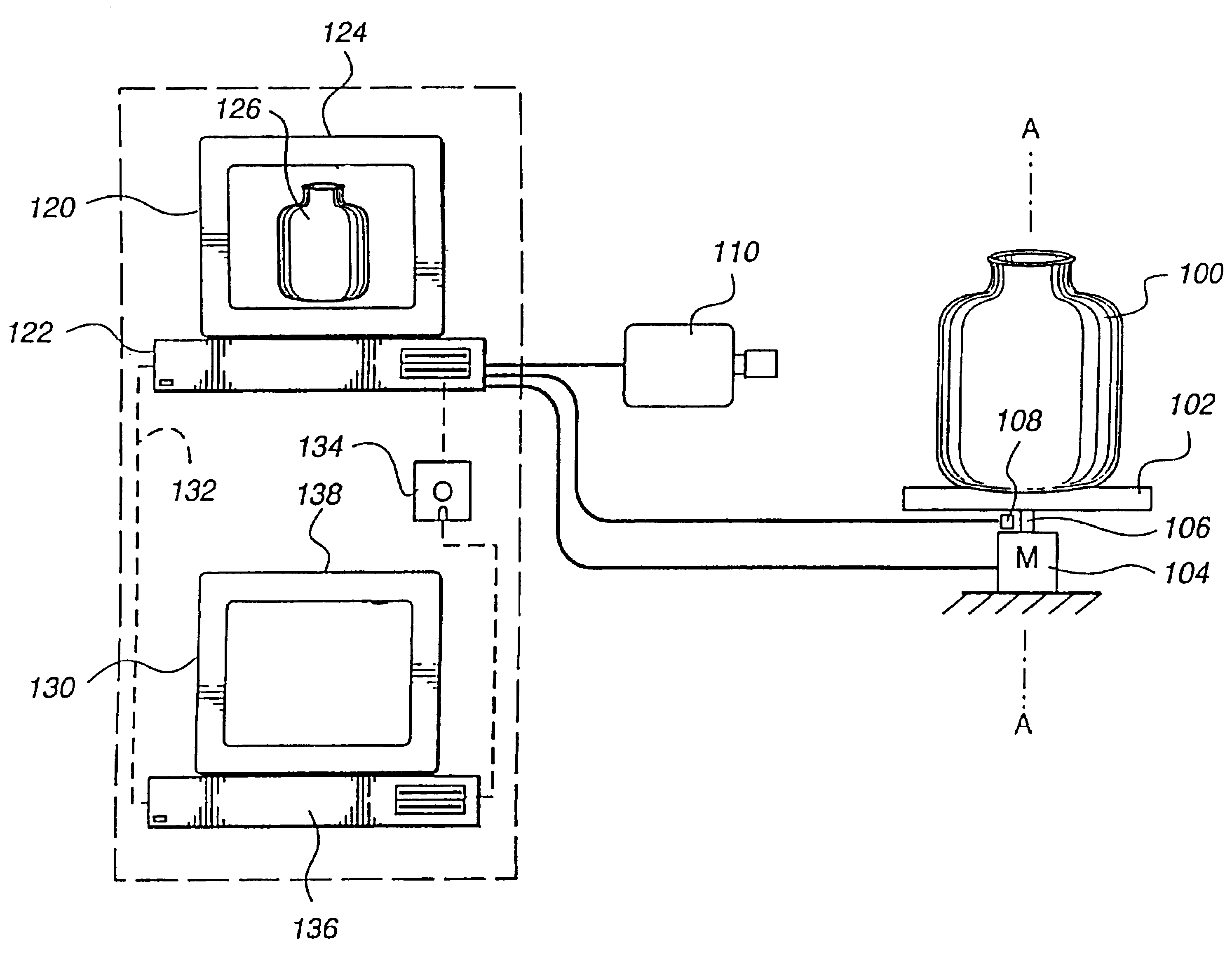
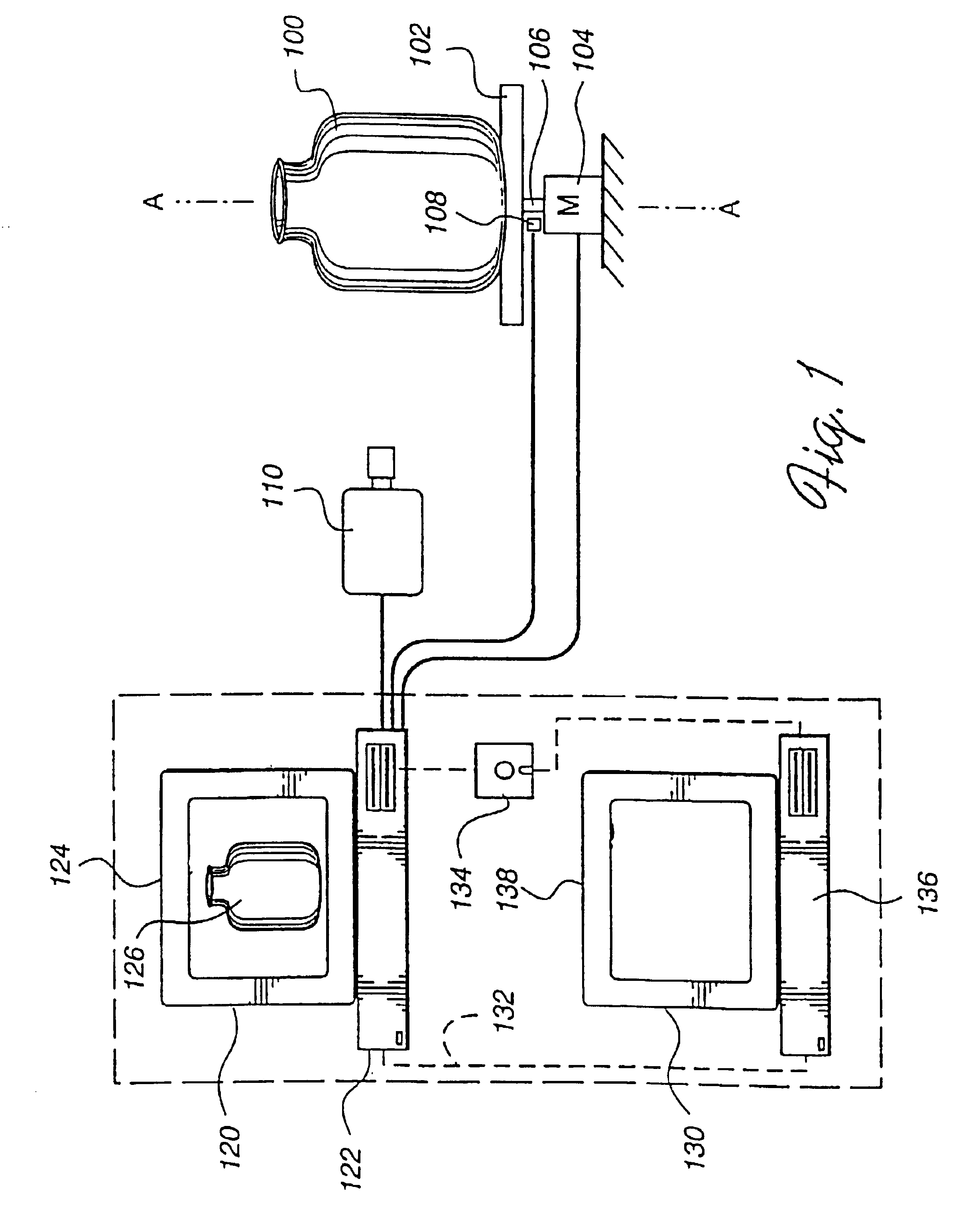
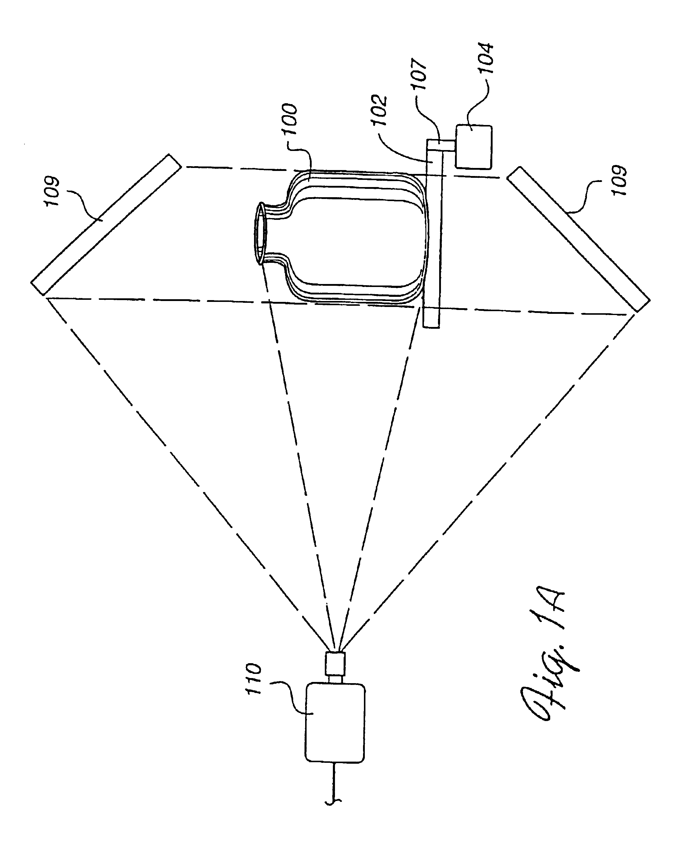
In FIG. 1, an embodiment of the present invention includes a system for obtaining a series of two dimensional color images of an object and processing those images to obtain a three dimensional model of the surface of the object. An object 100 which is to be digitized is placed on a rotatable platform 102. A motor 104 is provided to drive rotatable platform 102 via a shaft 106. A position encoder 108 detects the angular position of rotatable platform 102 and generates an electrical signal which represents the angular position of rotatable platform 102. An optical detector 110 (e.g. a color video camera) views object 100 and creates a two dimensional color image of object 100.

As object 100 is rotated by rotatable platform 102, detector 110 captures a series of color images of object 100. Each color image taken at a different time is associated with an angular rotation of object 100 about an axis of rotation, “A” which runs through shaft 106. Information about the angular position of ...


PUM


Abstract

Apparatus and method for creating 3D imagery of an object using calibration means to transfer data to a reference frame and visibility analysis to determine and resolve occlusion.

Description

TECHNICAL FIELDThis invention relates generally to optical scanners, and more particularly to optical scanners for providing a digital representation of three dimensional objects.BACKGROUND ARTMethods for successfully obtaining two dimensional (“2-D”) color image data for objects have been developed. This process is commonly known as two dimensional scanning or digitizing. When an object is scanned, a digital data file is created which contains image data including color information which is associated with a set of two dimensional points or coordinates. The color information is obtained by an optical detector or set of optical detectors that are typically organized in a one or two dimensional array.Matching the color information with the correct two dimensional point or location is not a significant problem in two dimensional scanning since the two dimensional point on which the optical detector is focused is the same point that is associated with the color information obtained by ...

Claims


Application Information

Patent Timeline
Patent Type & Authority Patents(United States)
IPC IPC(8): G01B11/00G06T7/00H04N13/00H04N13/221
CPCG01B11/00G06T7/0018G06T7/0065H04N13/0221H04N13/0246H04N13/0253G06T2207/10012H04N13/0055H04N2013/0081H04N13/0239H04N13/0242H04N13/0059G06T7/80G06T7/55H04N13/243H04N13/194H04N13/221H04N13/254H04N13/189H04N13/246H04N13/239
Inventor MUELLER, FREDERICK F.MIRAMONTI, JOHN L.SHI, JIANBO
Owner WAVEWORX
Learn More