Apparatus and method for measuring natural period of liquid

Inactive Publication Date: 2005-02-22
SEIKO EPSON CORP
View PDF14 Cites 41 Cited by
  • Summary
  • Abstract
  • Description
  • Claims
  • Application Information

AI Technical Summary

Benefits of technology

With such a configuration, even when a timing at which a liquid droplet is to be ejected cannot be ascertained accurately, the velocity of a liquid droplet can be measured with sufficiently high accuracy and sufficient durability.
Preferably, the apparatus fu

Problems solved by technology

However, there has not yet been realized an apparatus for measuring with sufficie

Method used


Image

  • Apparatus and method for measuring natural period of liquid
  • Apparatus and method for measuring natural period of liquid
  • Apparatus and method for measuring natural period of liquid

Examples


second embodiment

For this reason, by reference to FIG. 5 there will now be described the invention which takes such a case into particular consideration.

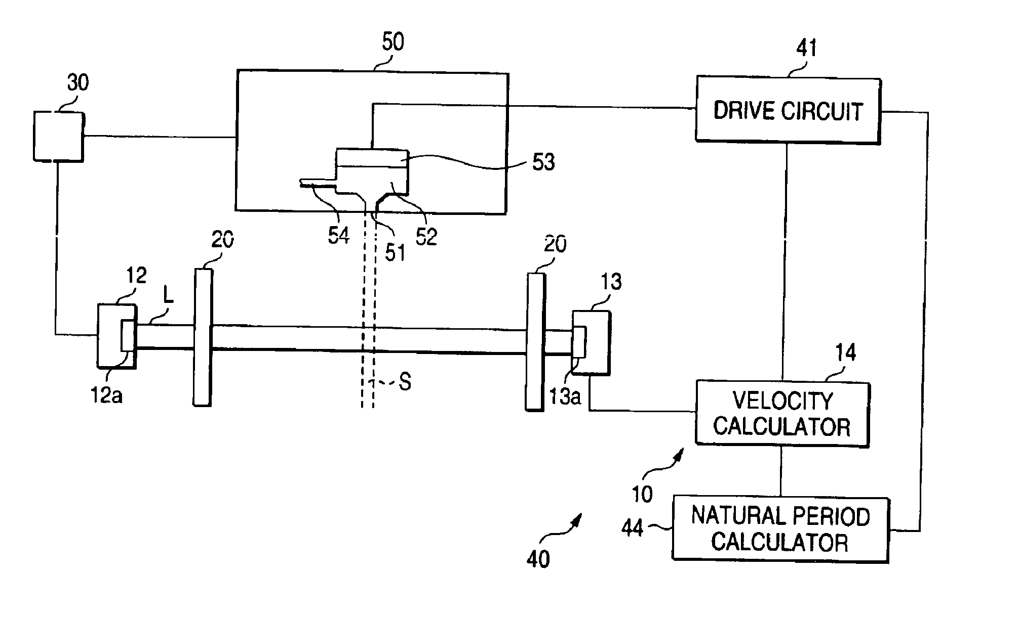
The velocity measuring apparatus 10 of the embodiment further comprises a second light emitter 12′ for emitting light on a second trajectory L' which crosses the space S across which a liquid droplet ejected from the nozzle orifice 51 passes; and a second light receiver 13′ for receiving light of the second trajectory L' crossing the passage space S.

More specifically, the second light emitter 12′ has a semiconductor laser 12a′, and the second light emitter 13′ has a photodiode 13a′. The light emitted from the semiconductor laser 12a′ is received by the photodiode 13a′ after crossing the passage space S.

The layout of a second trajectory L' of light (hereinafter called a “second light trajectory”), the passage space S, and the second light receiver 13′ is adjusted such that receipt of light performed by the second light receiver 13′ is interrupted whi...

third embodiment

the invention will now be described by reference to FIG. 7, as a configuration which yields the same advantage.

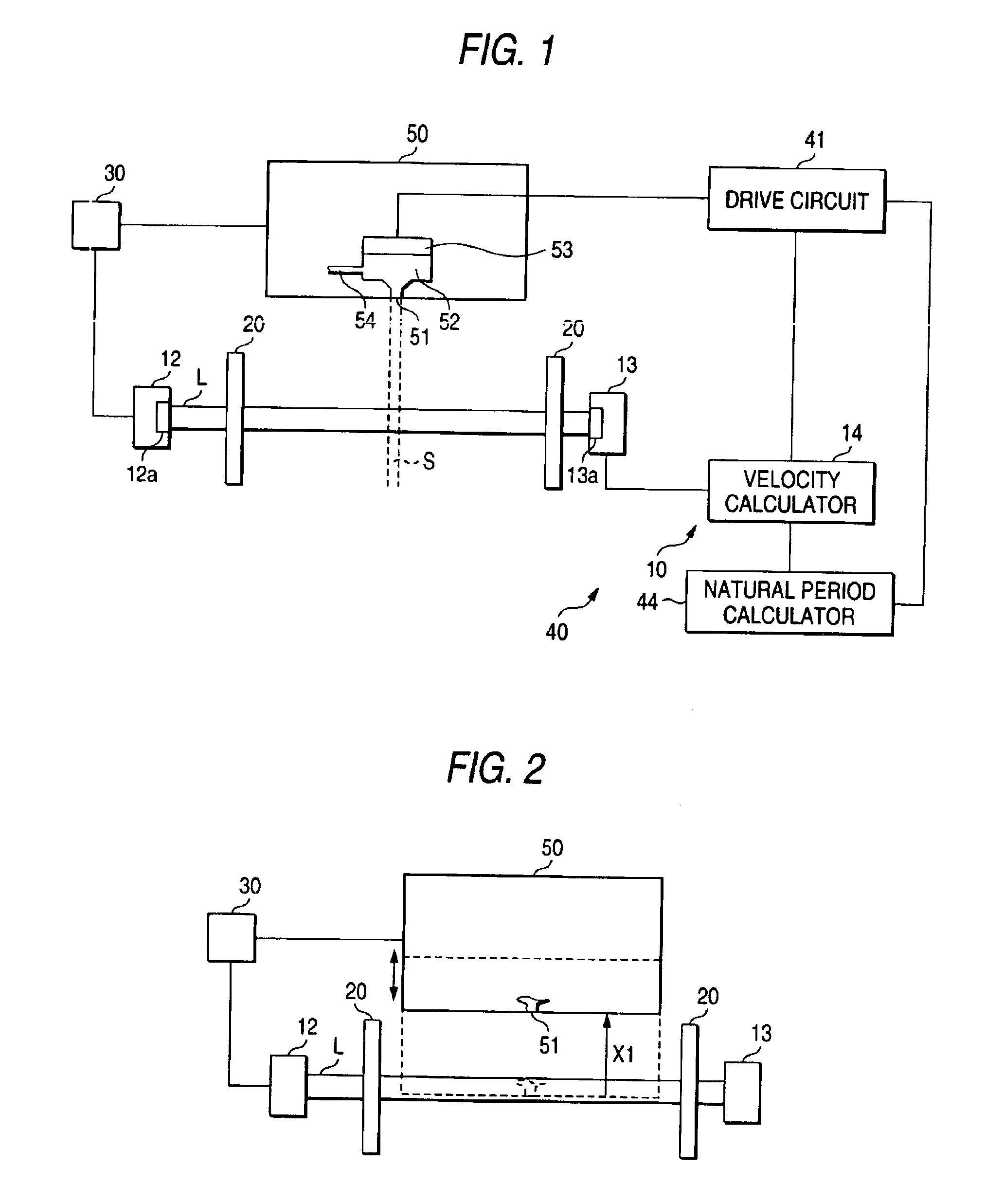
A position adjuster 30 of the embodiment shown in FIG. 5 is arranged so as to enable at least two ways of setting of a distance between the position of the nozzle orifice 51 of the head member 50 and the trajectory L of light originating from the light emitter 12. On the basis of the state of light received by the light receiver 13 according to the two ways of setting, the velocity calculator 14 derives the velocity of a liquid droplet ejected from the nozzle orifice 51.

In other respects, the velocity measuring apparatus of the embodiment is substantially identical with that of the second embodiment described by reference to FIG. 6. In the embodiment, those elements which are the same as those described in connection with the second embodiment are assigned the same reference numerals, and their detailed explanations are omitted.

In the embodiment, the ejection velocity of a ...

fifth embodiment

By reference to FIGS. 11 through 13, there will be described the invention that can preferably cope with such a case.

As shown in FIG. 11, the natural period measuring apparatus 40 of the embodiment comprises a pulse width extractor 18 which is interposed between the pulse width instrument 15 and the velocity calculator 14 and extracts a width wmax of the maximum pulse waveform for each drive signal. On the basis of the width wmax of the maximum pulse waveform, the velocity calculator 14 of the embodiment derives the velocity of a liquid droplet to be ejected from the nozzle orifice 51.

As shown in FIGS. 12 and 13 corresponding to FIGS. 9 and 10, according to the embodiment, even when a plurality of pulse waveforms P are produced as a result of presence of a satellite droplet, the width of the pulse waveform P corresponding to the main droplet can be ascertained at all times as the width wmax of the maximum pulse waveform. Accordingly, the natural period Tc of the liquid stored in the...


PUM


Abstract

In an apparatus for measuring a natural period of liquid in a pressure chamber formed in a head device which is provided with a nozzle orifice communicated with the pressure chamber and an actuator which varies pressure of the liquid contained in the pressure chamber, a driver generates a plurality of drive signals, each of which drives the actuator to eject a liquid droplet from the nozzle orifice under a condition different from the conditions established by the other drive signals. A light emitter emits a light beam so as to intersect a space through which the liquid droplet passes. A light receiver receives the light beam which has been passed through the space. A first calculator calculates an ejection velocity of the liquid droplet based on a timing at which the actuator is driven and a change in a photo-receiving state of the light receiver, with regard to every drive signal. A second calculator calculates a natural period of the liquid based on a change in the ejection velocity which is obtained from the plural drive signals.

Description

BACKGROUND OF THE INVENTIONThe invention relates to an apparatus for measuring a natural period of liquid in a pressure generating chamber disposed in a head member, wherein the head member comprises a nozzle orifice communicated with the pressure generating chamber storing liquid; a liquid supply channel for supplying liquid to the pressure generating chamber; and a piezoelectric member which deforms the pressure generating chamber, to thereby cause the nozzle orifices to eject liquid droplets. Such a head member is employed in various applications.For instance, a head member which ejects ink droplets as liquid droplets is used as a recording head of an ink jet recording apparatus for effecting recording on recording paper or the like.Measurement of a natural period of liquid stored in the pressure generating chamber of such a head member is useful for more accurate control of ejection of liquid droplets.However, there has not yet been realized an apparatus for measuring with suffi...

Claims


Application Information

Patent Timeline
IPC IPC(8): B41J2/04G01P3/64G01P3/68
CPCB41J2/04G01P3/68B41J2/125
Inventor HOSONO, SATORUTERAMAE, HIROFUMIENDO, HIRONORI
Owner SEIKO EPSON CORP
Why Eureka
Try Eureka