Device for position determination in sensorless motors

a sensorless motor and position determination technology, applied in the direction of motor/generator/converter stopper, electronic commutator, dynamo-electric converter control, etc., can solve the problem of not being able to evaluate the input voltage signal at the comparator, reducing the voltage difference at the comparator significantly, and supplying series pass transistors with parasitic capacities

Inactive Publication Date: 2005-02-22
ROBERT BOSCH GMBH
View PDF6 Cites 12 Cited by
  • Summary
  • Abstract
  • Description
  • Claims
  • Application Information

AI Technical Summary

Benefits of technology

It is therefore an object of the present invention to provide a new device for positio

Problems solved by technology

The disadvantage of this solution is the condition that the component element tolerances and temperature influences can drive the produced voltage drop so far from one another that the phase displacement which results from it can have influence on the power and the efficiency of the brushless direct current motors.
Moreover, the solution with the use of series pass transistors in the series branches has the disadvantage that the series pass transistors provided there have parasitic capacities.
Thereby the interference voltage difference at the comparator is significantly reduced, and at low rotary speeds of the brushless direct current moto

Method used


Image

  • Device for position determination in sensorless motors
  • Device for position determination in sensorless motors
  • Device for position determination in sensorless motors

Examples


Embodiment Construction

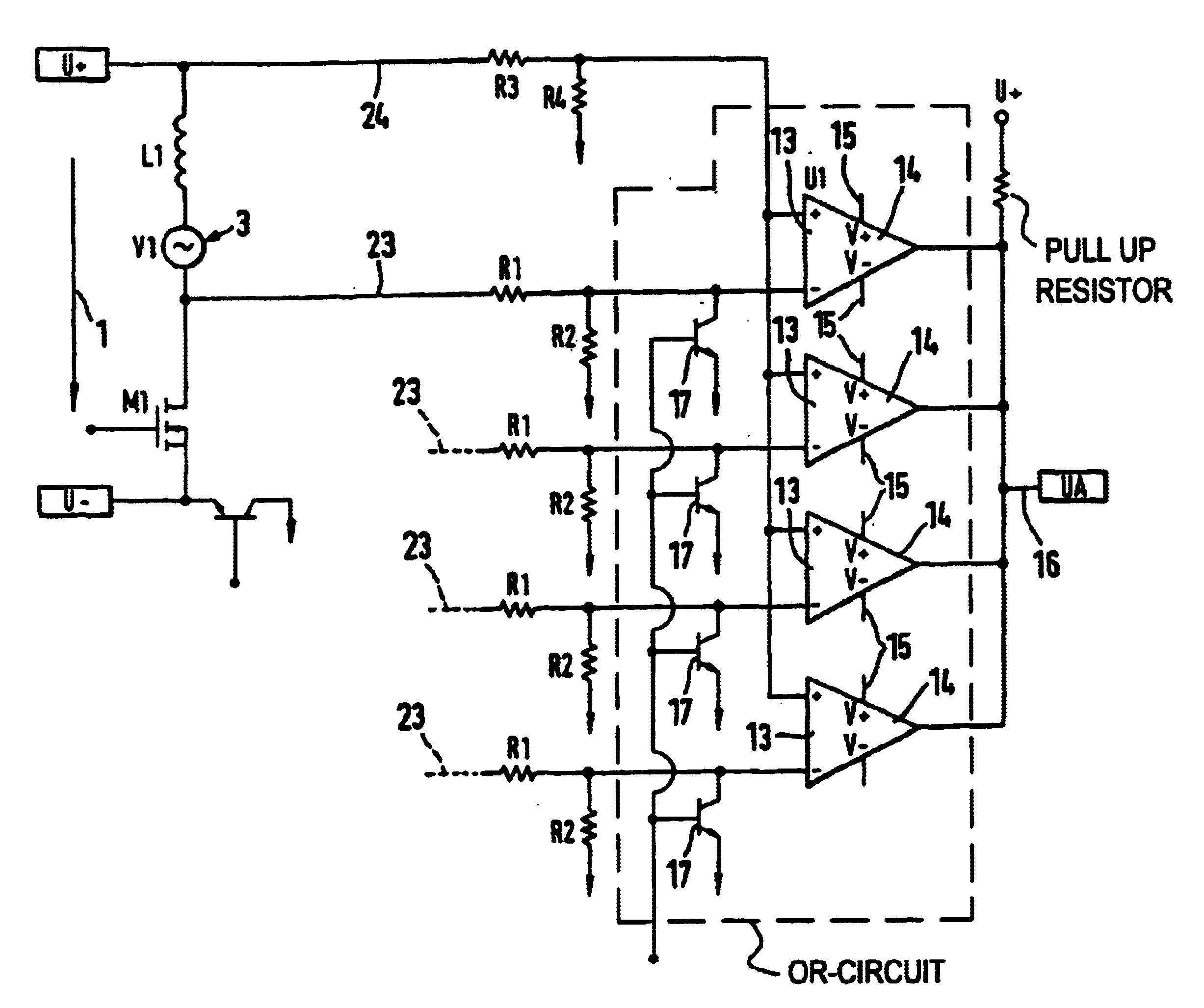
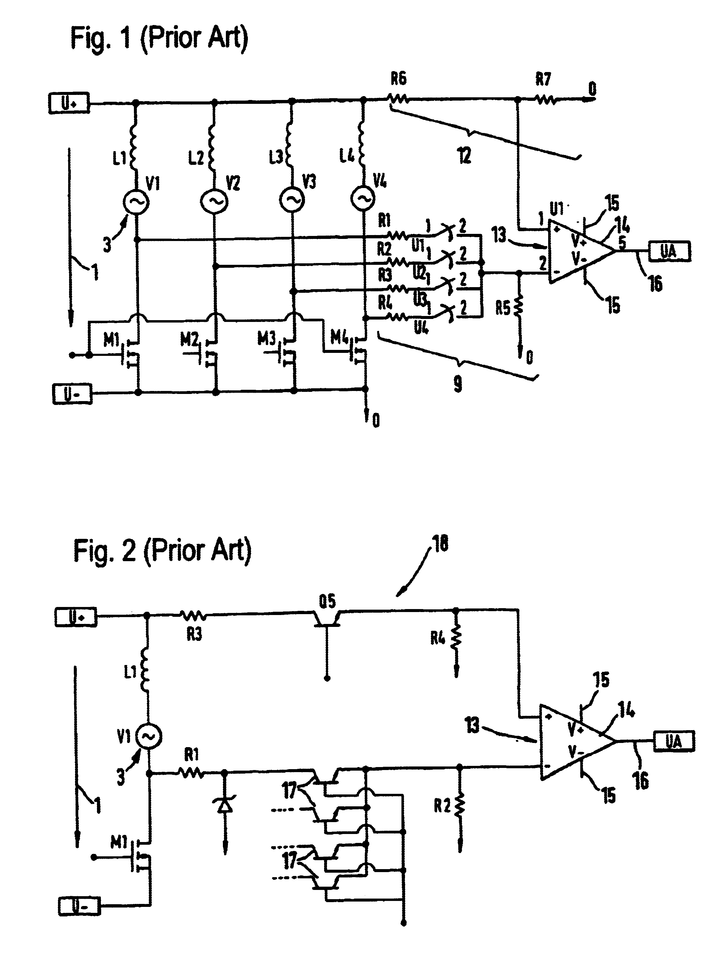
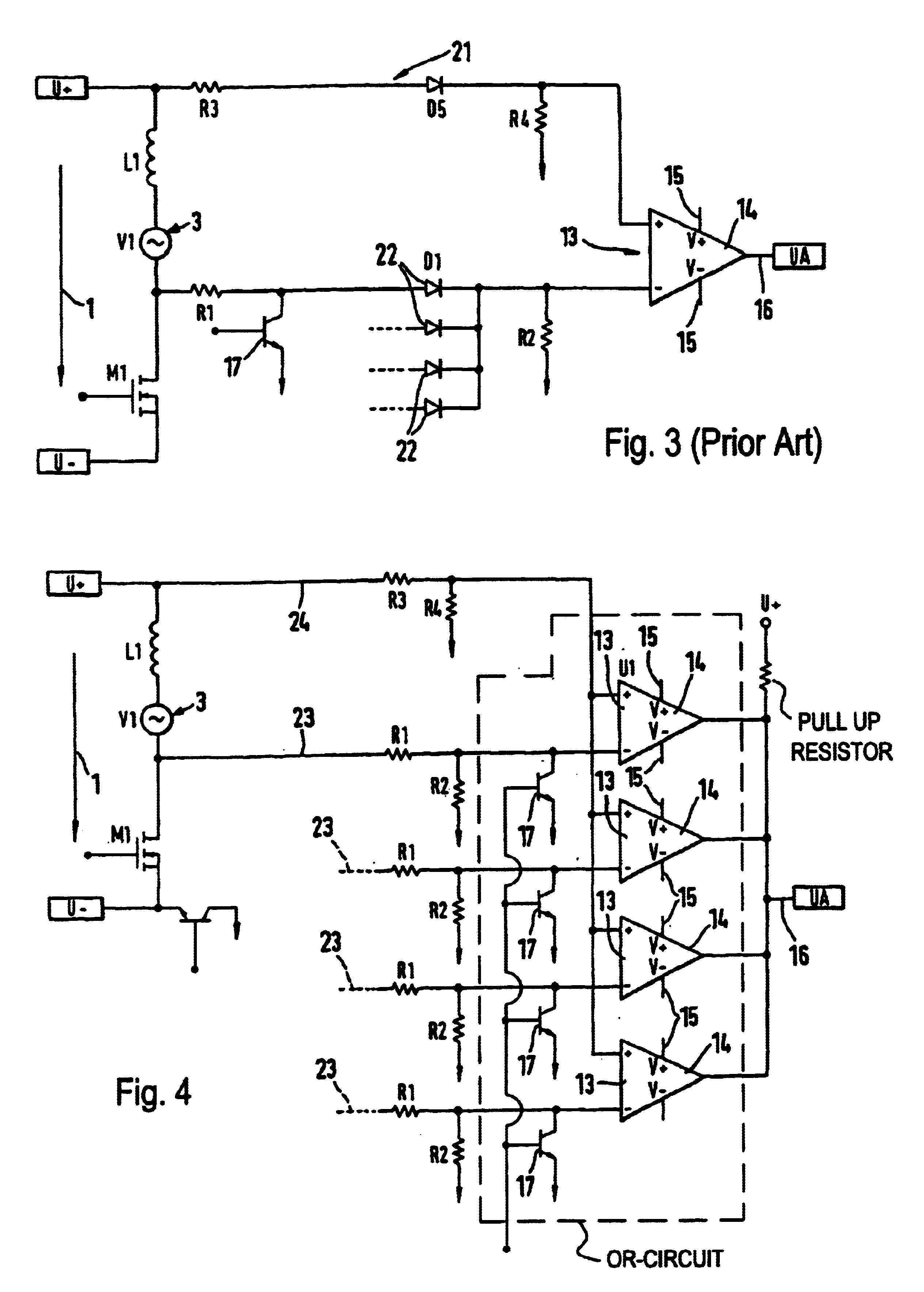
FIG. 1 shows a demultiplexer / comparator combination. It is set at each phase to be evaluated in a brushless direct current motor. Reference numeral 1 identifies the polarity of a voltage source. Inductivities 2 are provided with each phase to be evaluated, for example in a brushless direct current motor. They induce alternating counter voltages 3. The zero or zero crossover of the alternating voltages 3 allows for position determination to evaluate the position of the rotor in a brushless, sensorless direct current motor. As can be seen from FIG. 1, the resistors 4, 5, 6, 7 each with the resistor 8 form a first voltage divider 9, and the resistor 10 with the resistor 11 represent a second voltage divider 12. The both voltage dividers 9 and 12 have the same divider ratio, to adapt the induced counter voltages 3 in the phases of the sensorless, brushless current motor to be evaluated to the input direct cycle region of the comparator component 14. Reference numeral 15 at the comparato...


PUM


Abstract

A device for position determination in a sensorless direct current motor has a plurality of inductivities arranged in corresponding phases and inducing alternating voltages in a motor windings, a plurality of resistances located in phase branches to be evaluated for a position determination of a rotor position of the sensorless direct current motor, and a plurality of comparator components each associated with the corresponding phase branch to be evaluated.

Description

BACKGROUND OF THE INVENTIONThe present invention relates to a device for position determination in sensorless motors.In electrical machines such as electric motors, for example brushless direct current motors, which have no additional sensors for position determination of the rotor, the counter voltage UEMF of the motor winding by the electric motor force (EMF) is evaluated. The actual position of the rotor of the brushless direct current motor can be determined via the zero crossing of the alternating voltage UEMF. In brushless direct current motors with several phases, the induced counter voltages of several phases are evaluated for position determination of the rotor.Brushless direct current motors as a rule are provided with several phases, in which the corresponding induced counter voltages can be utilized for position determination of the actual rotary position of the rotor of the electric motor. For this purpose a demultiplexer is utilized, with which the phase which is to be...

Claims


Application Information

Patent Timeline
IPC IPC(8): G01P3/42G01P3/48H02P6/12H02P6/18H02P6/14H02P6/182
CPCG01P3/48H02P6/182H02P6/12Y10S388/923
Inventor KESSLER, MARTINFRANK, ULRICH
Owner ROBERT BOSCH GMBH
Why Eureka
Try Eureka