Horn antenna

a horn antenna and antenna technology, applied in antennas, engine lubrication, liquid/fluent solid measurement, etc., can solve the problems of increased difficulty in condensation and soiling, increased difficulty in dampening and reflection of microwaves, and worsening of antenna gain and the level of side lobes

Inactive Publication Date: 2005-02-22
ROSEMOUNT TANK RADAR
View PDF17 Cites 210 Cited by
  • Summary
  • Abstract
  • Description
  • Claims
  • Application Information

AI Technical Summary

Benefits of technology

According to an aspect of the invention is presented a horn antenna at a radar level gauge for determination of a surface level of a medium stored in a tank. The antenna is intended for transmission and reception of microwaves using a microwave unit arranged at the roof of the tank. The antenna comprises a first conductive housing with a wave guide port which is connectable to a wave guide, a first aperture which is separate from the wave guide port and a first divergent section between said wave guide port and the first aperture. A dielectric body is arranged within and essentially filling the first conductive housing, which body has a free end in the area of the first aperture. The horn antenna is characterized in that a locking device is arranged around the first aperture, which locking device is arranged to affix the dielectric body inside the first housing and that in the area of the locking device is arranged at least one flexible sealing element between the dielectric body and the first housing. The invention thereby provides a device for efficiently separating the atmospheres inside and outside the tank while maintaining a mechanically pressure resistant antenna design and an efficient microwave performance.
In accordance with a second aspect of the invention is presented a method for achieving a horn antenna which is mechanically constituted such that the horn antenna will withstand the environment present inside the tank in the form of pressure variations and contaminating substances. The method comprises making a first divergent conductive housing with a wave guide port which is attachable to a wave guide, a first aperture which is separate from the wave guide port and a divergent section between the wave guide port and the first aperture. A dielectric body is affixed inside and essentially filling the first housing such that a first end of the dielectric body appears in the area of the first aperture. A locking device is arranged around the first aperture, whereby the dielectric body is fixed in the first housing. A flexible sealing element is arranged between the dielectric body and the first housing in the area of the locking device. The invention thereby provides one way of efficiently separating the atmospheres inside and outside the tank while maintaining a mechanically pressure resistant antenna design and an efficient microwave performance.

Problems solved by technology

Still a certain phase error of the microwaves transmitted from or received by the antenna at the opening remains which worsens the antenna gain and the level of the side lobes.
However, in combination with impurities and condensation difficulties with dampening and reflection of microwaves remain, as the antenna is covered with a layer of impurities or condensation.
Through the smaller dimensions of the antenna horn the difficulties with condensation and soiling are increased.
Condensation in the form of e.g. water, in this case leads to increased dampening.
A horn having a process window is less sensitive to condensation and soiling but it is not able to resist pressure as well as the horn lacking a process window.
On the other hand the mechanical properties are not the best.
The atmosphere in the tank may contain substances that could cause corrosion, explosion, health risks, and environmental damage.
However, the document does not address the problem of preventing leakage from the tank through the antenna to the outside of the tank.

Method used


Image

  • Horn antenna
  • Horn antenna
  • Horn antenna

Examples


first embodiment

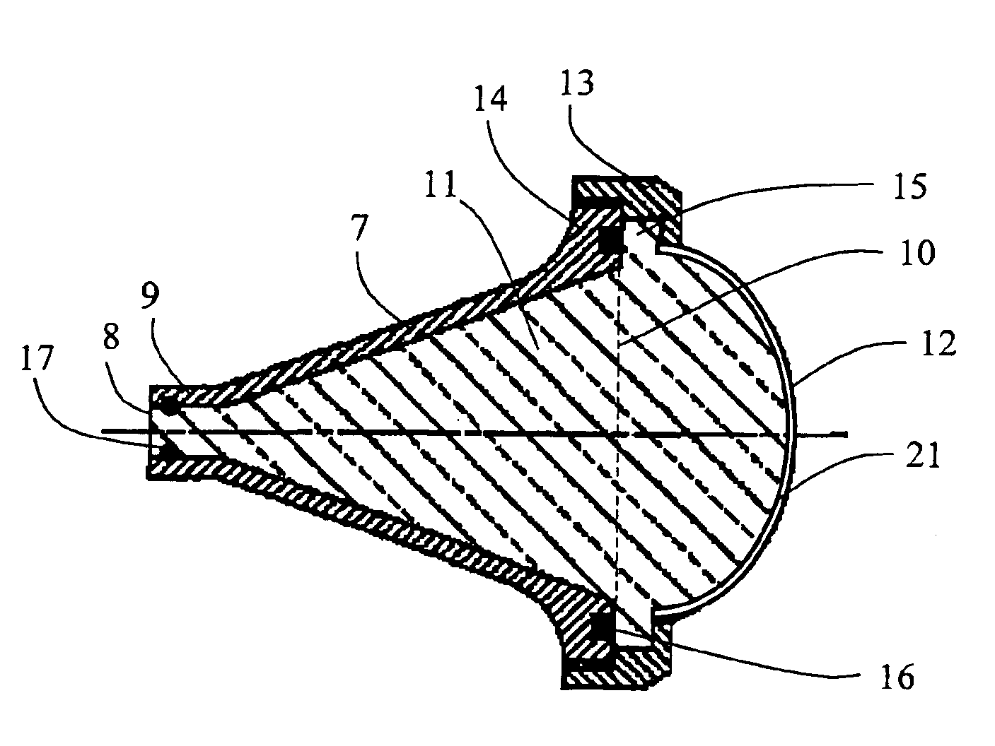
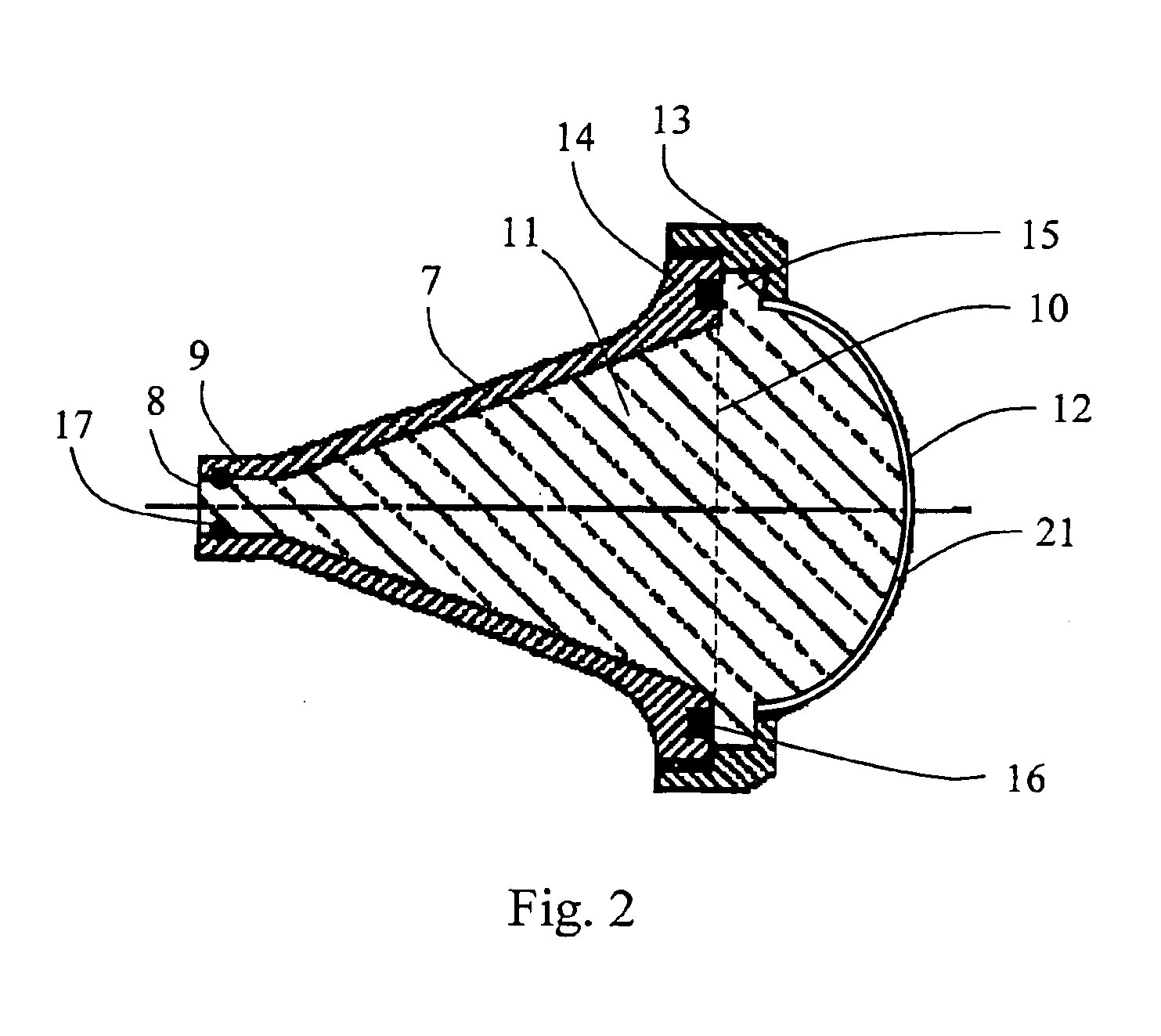
FIG. 2 Shows a section through a horn antenna in accordance with the present invention.

second embodiment

FIG. 3 Shows a section through a horn antenna in accordance with the present invention.

third embodiment

FIG. 4 Shows a section through a horn antenna in accordance with the present invention.

DESCRIPTION OF EMBODIMENTS

An example of an embodiment will be given with reference to the attached drawings.

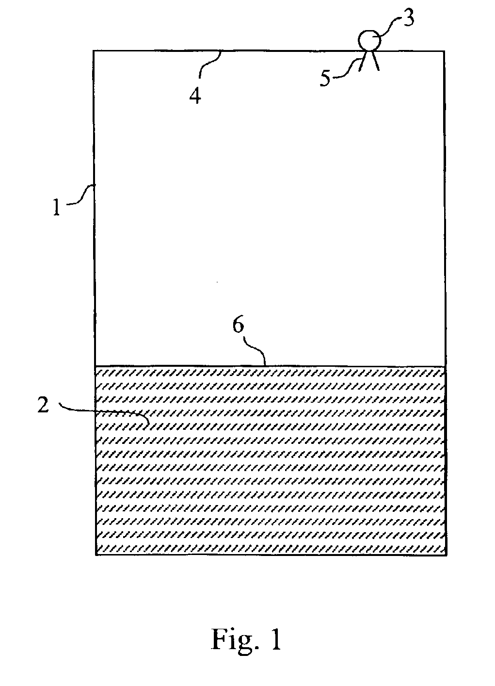
The principle of a radar level gauge is shown in FIG. 1. A tank 1 is used for storing a medium 2. The medium can be a fluid, such as oil, refined products and gas in the liquid state, or a particulate material, i.e. a pulverized solid state substance. A radar 3 is arranged at the roof 4 of the tank 1, wherefrom a microwave beam is transmitted from the radar via an antenna 5 at the inside of the tank. The emitted beam is reflected from the surface 6 of the medium and received by the antenna 5. Through a comparison and evaluation of the time delay between the transmitted signal and the reflected signal, in an evaluation and control unit, a determination of the surface 6 level of the medium can be made using known procedures.

FIG. 2 shows a first embodiment of the horn antenna in accordance with...


PUM


Abstract

The present invention relate to a horn antenna at a radar level gauge for determination of a level of a surface of a medium stored in a tank and a method of making a horn antenna which is mechanically constituted such that the horn antenna will withstand the environment of the tank interior. The antenna comprises a first conductive housing (7) having a wave guide port (8), which is connectable to a wave guide, a first aperture (10), which is separated from the wave guide port (8) and a fist divergent section between the wave guide port (8) and the first aperture (10). A dielectric body (11) is arranged inside and essentially filling the first conductive housing (7), which body (11) displays a free end (12) in the area of the first aperture (10). The horn antenna is characterized in that around the first aperture (10) is arranged a locking device (13), which is arranged to fix the dielectric body (11) in the first housing (7) and that in the area of the locking device (13) is arranged at least one flexible sealing element (16) between the dielectric body (11) and the first cover (7).

Description

TECHNICAL FIELD OF THE INVENTIONThe present invention relates to a horn antenna for use with a level gauge utilizing a radar for determination of a surface level of a medium stored in a tank, whereby the invention discloses both a device and a method for achieving a horn antenna which is mechanically constituted such that the horn antenna will withstand the environment inside the tank in the form of pressure variations and contaminating substances in order to prevent contamination of the antenna and leakage to the outside of the tank.RELATED ARTIt is previously known to gauge a surface level of a medium stored in a tank using radar level gauges. An example of such a device is given by the patent document U.S. Pat. No. 4,665,403. At a device of the type disclosed by the referenced document, a pipe, which communicates with the medium of the tank, is utilized as a wave guide for the microwaves which are transmitted from a radar unit and which are received by the same radar unit after b...

Claims


Application Information

Patent Timeline
Patent Type & Authority Patents(United States)
IPC IPC(8): G01F23/284H01Q1/22H01Q19/08H01Q13/00H01Q19/00H01Q13/02
CPCG01F23/284H01Q1/22H01Q19/09H01Q13/02H01Q19/08H01Q1/225
Inventor OHLSSON, MAGNUS
Owner ROSEMOUNT TANK RADAR
Why Eureka
Try Eureka