Adaptive compensation method for an anti-lock brake control

Inactive Publication Date: 2005-02-22
GM GLOBAL TECH OPERATIONS LLC
View PDF19 Cites 10 Cited by
  • Summary
  • Abstract
  • Description
  • Claims
  • Application Information

AI Technical Summary

Benefits of technology

The present invention is directed to an improved anti-lock control method for a vehicle brake system, wherein various factors that degrade the effectiveness of the brake system are identified and used to adaptively determine a brake apply rate during anti-lock brake control. In the illustrated embodiment, the identified factors include fading due to brake heating, hydraulic leakage, mis-adjusted and non-releasing rear brakes, brake wear and excessive vehicle weight, and the adaptively-determined brake apply rate compensates for the identified brake system degradation so that the optimal tractive force during anti-lock brake control is more nearly realized.

Problems solved by technology

However, the control strategies assume that the brake system is operating normally, and the system performs at a sub-optimal level when the braking effectiveness is degraded due to fluid leakage, fading, poor adjustment, wear, and so forth.

Method used


Image

  • Adaptive compensation method for an anti-lock brake control
  • Adaptive compensation method for an anti-lock brake control
  • Adaptive compensation method for an anti-lock brake control

Examples


Embodiment Construction

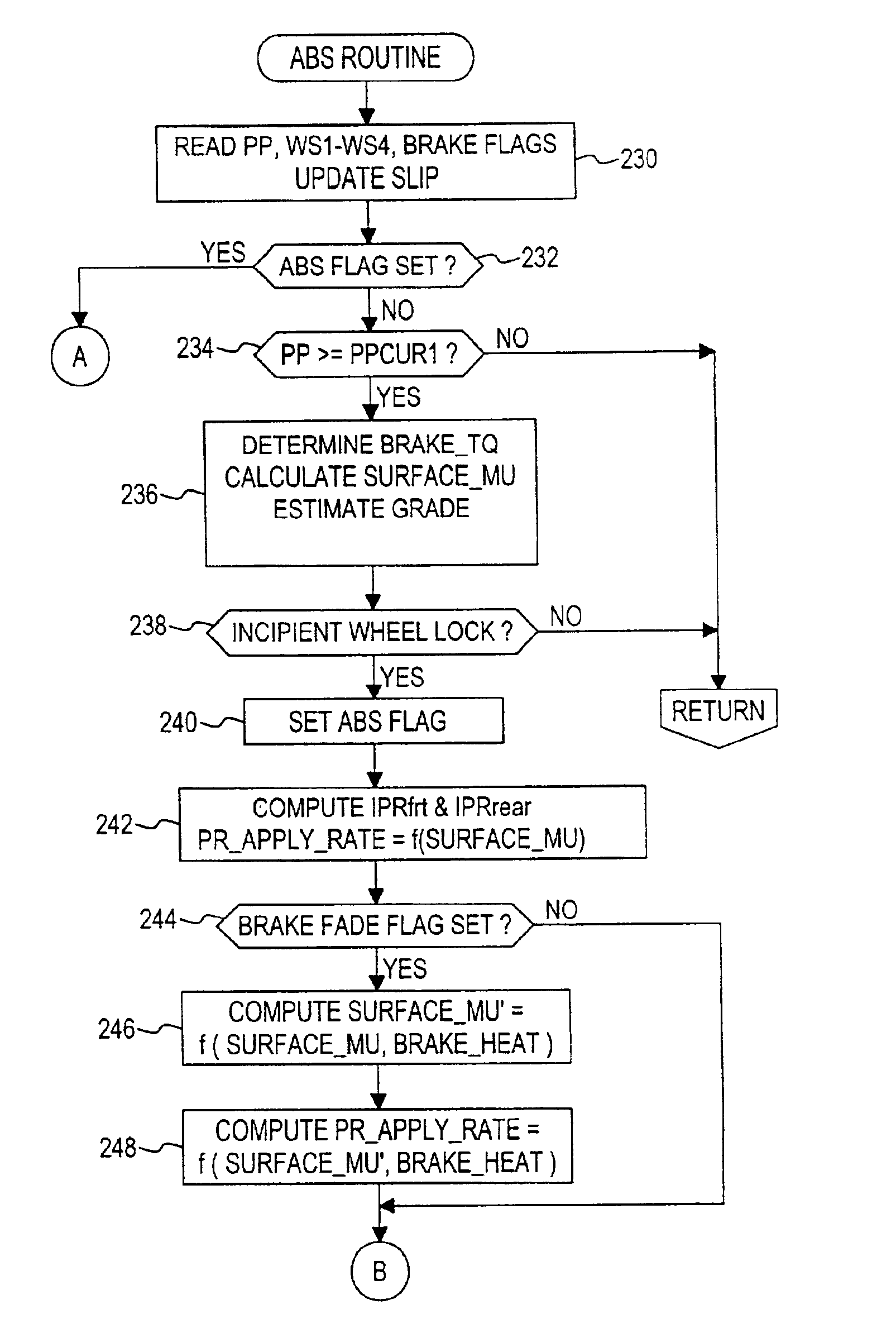
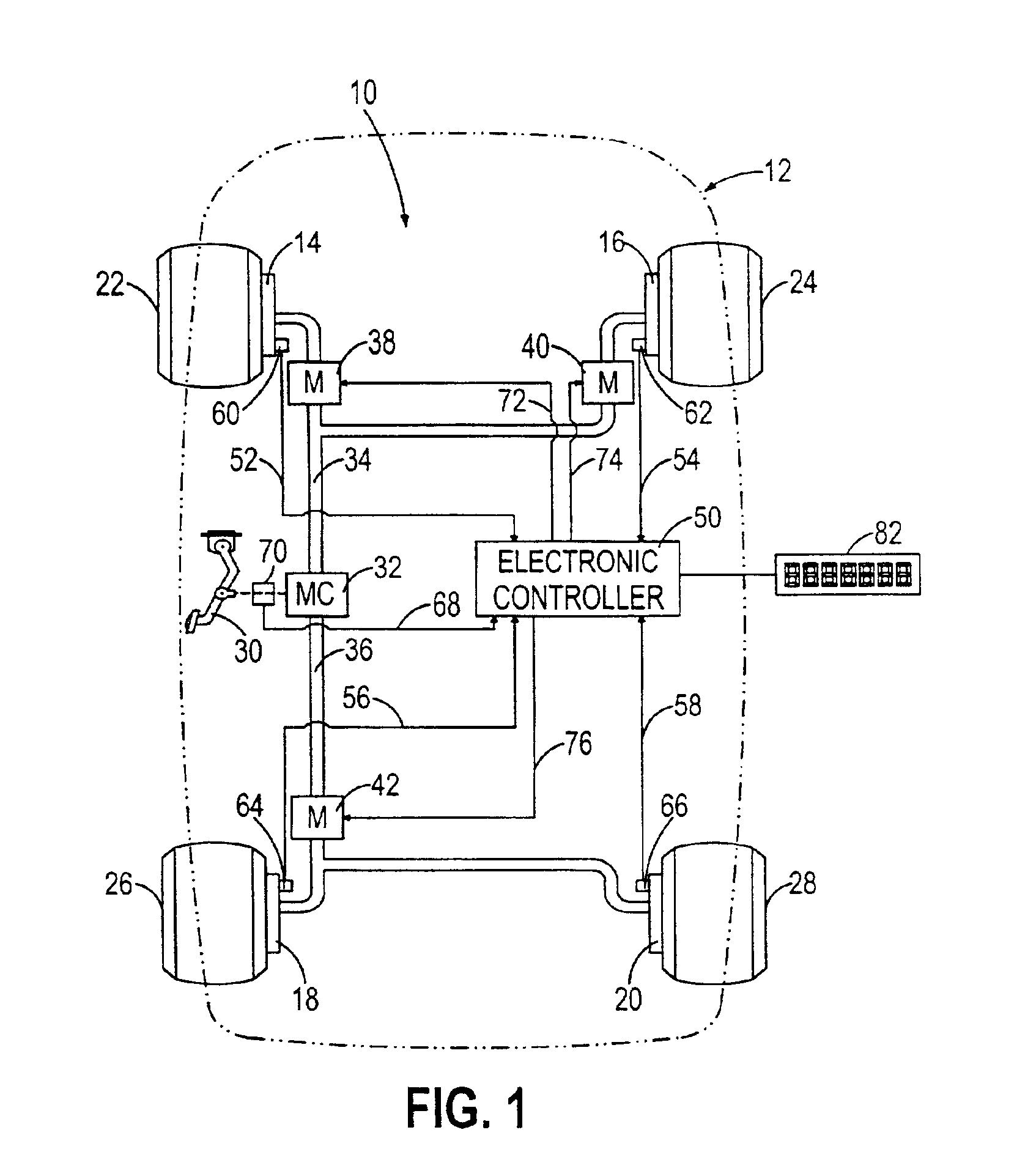
Referring to FIG. 1, the present invention is disclosed in the context of an anti-lock braking system 10 for a vehicle 12 having hydraulically activated friction brakes 14, 16, 18, 20 at each of four vehicle wheels 22, 24, 26, 28. In mechanizations where the rear brakes 18, 20 are drum brakes, a self-adjusting mechanism (not shown) is included to compensate for brake shoe wear during braking while the vehicle 12 is backing up. A driver-manipulated brake pedal 30 is mechanically coupled to a master cylinder (MC) 32 for producing hydraulic pressure in proportion to the force applied to pedal 30. Master cylinder 32, which may include a pneumatic booster (not shown), proportions the hydraulic pressure between front and rear brake supply lines 34 and 36 in a conventional manner. Front supply line 34 is coupled to the left front service brake 14 via left-front anti-lock modulator (M) 38, and to the right front service brake 16 via right-front anti-lock modulator (M) 40. Rear supply line 3...


PUM


Abstract

An improved anti-lock control method for a vehicle brake system identifies various factors that degrade the effectiveness of the brake system and adaptively adjusts a brake apply rate during anti-lock brake control to compensate for the identified degradation so that the optimal tractive force during anti-lock brake control is more nearly realized. The identified factors include fading due to brake heating, hydraulic leakage, mis-adjusted and non-releasing rear brakes, brake wear and excessive vehicle weight.

Description

TECHNICAL FIELDThis invention relates to motor vehicle anti-lock brake systems, and more particularly to a control method that adaptively adjusts an anti-lock brake pressure apply rate to compensate for a detected degradation of braking effectiveness.BACKGROUND OF THE INVENTIONA motor vehicle anti-lock braking system (referred to herein as an ABS system) repeatedly releases and re-applies hydraulic brake pressures during conditions of wheel lock with the objective of maximizing the tractive force between the vehicle tires and the road surface. However, the control strategies assume that the brake system is operating normally, and the system performs at a sub-optimal level when the braking effectiveness is degraded due to fluid leakage, fading, poor adjustment, wear, and so forth. Accordingly, what is needed is an anti-lock brake control method that adaptively compensates for degraded braking effectiveness.SUMMARY OF THE INVENTIONThe present invention is directed to an improved anti-...

Claims


Application Information

Patent Timeline
Patent Type & Authority Patents(United States)
IPC IPC(8): B60T8/88B60T8/1763B60T8/34B60T8/50B60T8/17
CPCB60T8/17636B60T8/50B60T8/885B60T2270/602B60T2270/403
Inventor WALENTY, ALLEN JOHNLEPPEK, KEVIN GERARDTHATCHER, DAVID ALAN
Owner GM GLOBAL TECH OPERATIONS LLC
Why Eureka
Try Eureka