Method and system for regulating a stability control system of a vehicle

Inactive Publication Date: 2005-02-22
MICHELIN RECH & TECH SA
View PDF18 Cites 19 Cited by
  • Summary
  • Abstract
  • Description
  • Claims
  • Application Information

AI Technical Summary

Benefits of technology

As can be seen, the invention provides a method for regulating a system for controlling the stability of a vehicle based on the forces acting at the center of each wheel of the vehicle. More specifically, the actions of the driver, whether they involve steering, accelerating or braking, will be reflected in forces (changes in forces) transmitted by the tires to the ground. Depending on whether or not these force variations are compatible with respect to the commands of the driver, it may be concluded whether or not the vehicle is stable. The origin of future displacements is found starting from the forces acting on the ground. In this way it is possible to correct the path of the vehicle much sooner and an ESP sy

Problems solved by technology

If the driver, basically as a result of his handling of the steering wheel, drives the vehicle beyond the limits of stability, the vehicle will exhibit oversteering or understeering.
Moreover, the currently available ESP system observes only the movements of the body of the vehicle without knowing specifically the exact reasons for the loss of control.
The system will detect a displacement of the vehicle not in accord with the command given by the driver, more slowly the greater the inertia of the vehicle, and the necessary correction will be all the more difficult the greater the inertia.
Furthermore, the detection of yaw movements requires the use of costly sensors.
If on the other hand it is the cornering force of the rear axle that first becomes saturated, then the vehicle will oversteer since the cornering forces of the rear train are less than the fo

Method used


Image

  • Method and system for regulating a stability control system of a vehicle
  • Method and system for regulating a stability control system of a vehicle
  • Method and system for regulating a stability control system of a vehicle

Examples


Example

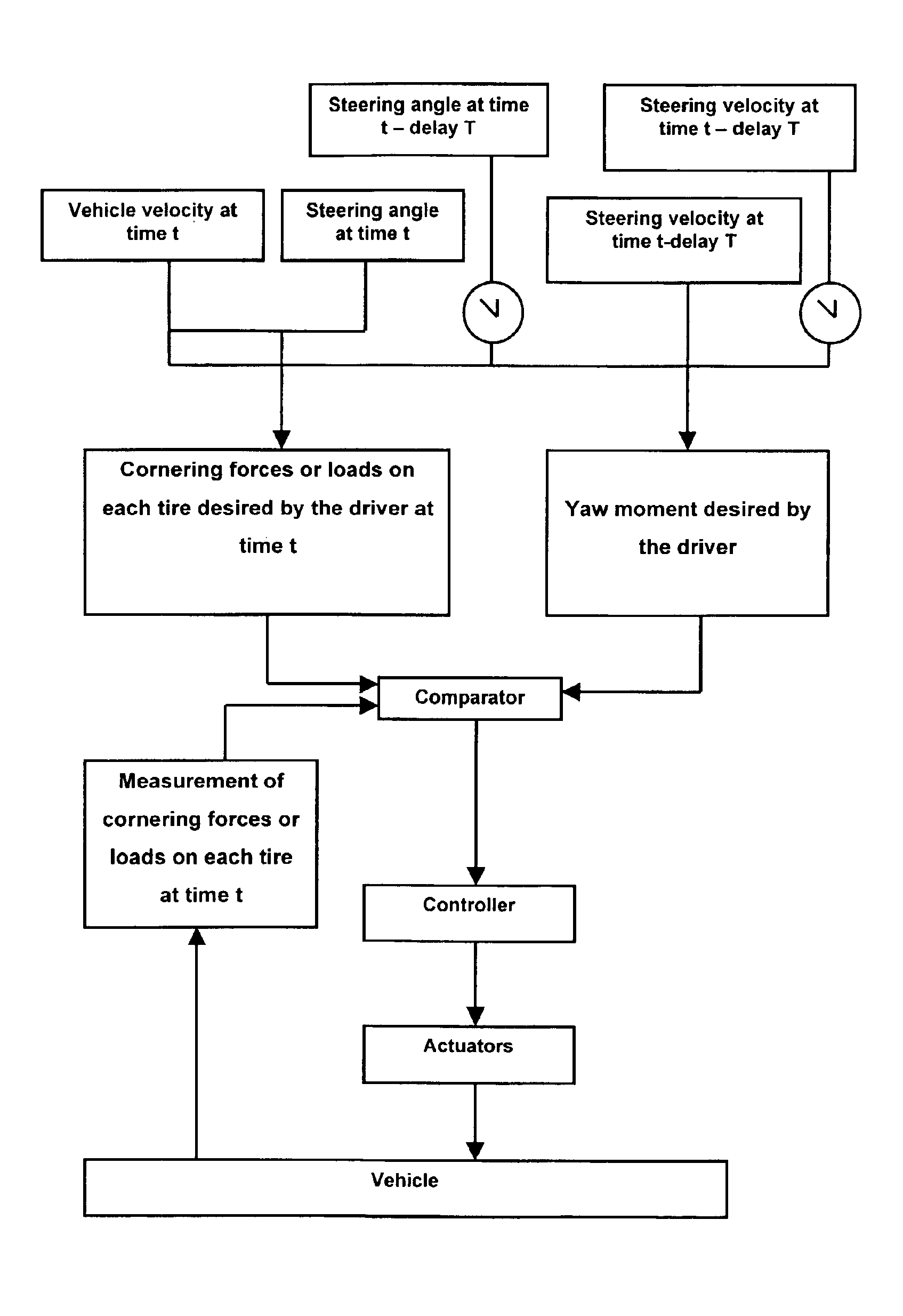
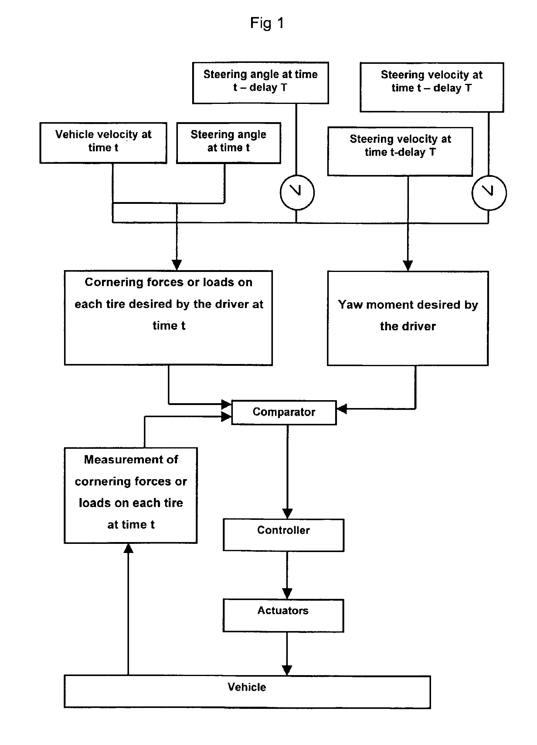
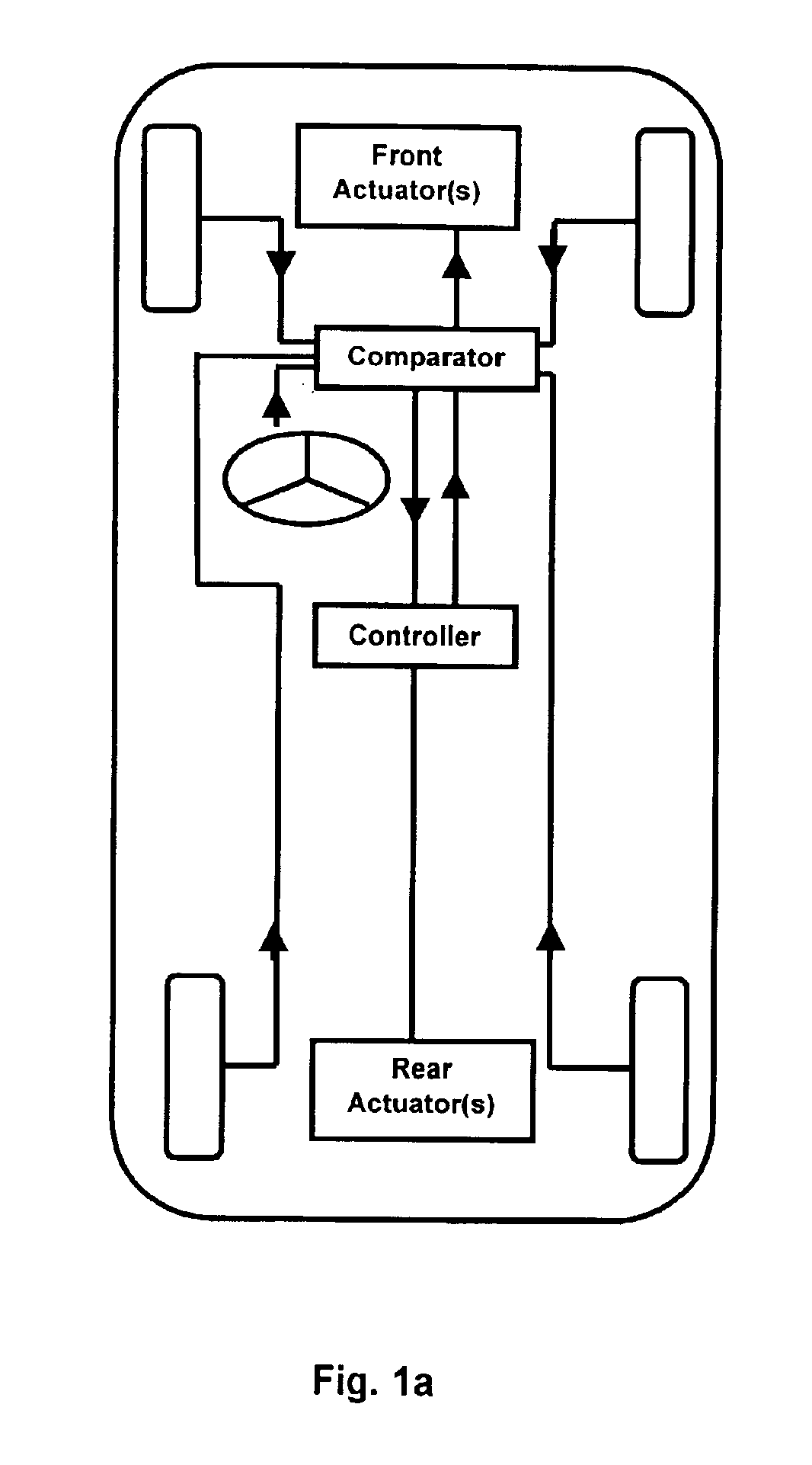
We shall start from the fact that, at a given velocity, an angle at the steering wheel imposed by the driver may be interpreted as a cornering force or load instruction, or as a yaw moment instruction on the vehicle. This is shown diagrammatically in the upper part of FIG. 1. Furthermore, it has been seen that in order to implement the present invention, it is necessary to have measurements of the actual cornering forces (cornering forces of the tires or elastic tire casings used in the ground contacting arrangement). This is illustrated in the left-hand section, starting from “vehicle,” in FIG. 1. In the case where it is desired to act on the distribution of the loads (see other explanations below concerning the effect on the yaw moment of the distribution of the loads), it is necessary to have measurements of the actual loads.

The diagram in FIG. 1 superimposes several methods: either the actions of the driver at a given moment and the preceding actions are interpreted as a demand ...


PUM


Abstract

The invention proposes a method for regulating a stability control system of a vehicle based on the forces acting at the center of each wheel of the vehicle. The actions of the driver, i.e. steering, acceleration or braking, produce forces (changes in forces) are transmitted by the tires to the ground. Control of the operating means of the vehicle (active anti-roll device, engine torque, braking torque, load per wheel or direction) utilizes instructions resulting from the actions of the driver to apply forces. The invention proposes a method of expressing, in terms of forces, the inputs of the driver as a function of the inertia of the vehicle body, velocity of forward movement of the vehicle, and angle at the steering wheel (steering wheel velocity and steering wheel acceleration). If the actual forces that are measured do not correspond to the forces desired by the driver, the active system compensates for this difference by acting on the force distributions in the chassis.

Description

BACKGROUND AND SUMMARY OF THE INVENTIONThe present invention relates to systems for controlling the stability of a vehicle, commonly known as ESP (Electronic Stability Program) systems.In safety systems for vehicles it is necessary to be able to assess the behavior of the vehicle in real time. This is the basis of the so-called ESP systems for controlling stability. These systems currently rely on, inter alia, monitoring movements of the vehicle by installing sensors to measure the transverse acceleration of the vehicle and the yaw rate of the vehicle.When moving under good safety conditions, that is, when the stability of the vehicle is not compromised, the vehicle obeys the driver's commands. If the driver, basically as a result of his handling of the steering wheel, drives the vehicle beyond the limits of stability, the vehicle will exhibit oversteering or understeering. The vehicle turns, that is, performs a yaw movement, in excess of that desired by the driver (oversteering) or...

Claims


Application Information

Patent Timeline
IPC IPC(8): B60T8/1755B60T8/17B62D6/00
CPCB60T8/1755B62D6/003B60T2270/86B60T2260/02
Inventor PALLOT, PATRICK
Owner MICHELIN RECH & TECH SA
Why Eureka
Try Eureka