Computer-implemented automated building design and modeling and project cost estimation and scheduling system

a technology of project cost estimation and scheduling system, applied in the field of computer-implemented automated building design and modeling, to achieve the effects of reducing building delivery time, eliminating many on-site redesign issues, and speeding up the production of requisite documents

Inactive Publication Date: 2005-02-22
BECK TECH
View PDF8 Cites 310 Cited by
  • Summary
  • Abstract
  • Description
  • Claims
  • Application Information

AI Technical Summary

Benefits of technology

[0028]Yet another technical advantage achieved with the invention is that different data sets for implementing multiple design configurations may be input to the system along with incremental steps by which they are to vary. Assembly of all of the resultant building models occurs automatically in sequence such that they can be compared and the optimum building model selected. This process is referred to as “rattling the box” and enables multiple designs to be compared and evaluated and the optimum design to be selected therefrom.
[0029]Yet another technical advantage achieved with the invention is the reduction in building delivery times resulting from the speedier production of the requisite documents, as well as the elimination of the many on-site redesign issues that typically occur during the construction of a building due to poorly coordinated information being generated at the design document stage.
[0030]Yet another technical advantage achieved with the invention is the increase in quality achieved in the design documents due in part to the guaranteed coordination of the information, as well as the time reduction and automation in the document production process, which enables many more drawings and details to be produced than would typically be feasible. This array of extra information helps deliver a far more complete document set, which in turn enables more efficient management of the construction process.
[0031]Still another technical advantage achieved with the invention is its ability to automatically generate a fully coordinated building design by encapsulating the knowledge and expertise of the designers and engineers, and the rules and codes of the construction industry specialists and regulatory bodies.
[0032]Still another technical advantage achieved with the invention is that the detailed design information may be entered into the DMES system via a manual graphical design interface, instead of through the element and massing element dialogs boxes, thus facilitating use of the DMES system by architects and engineers, who will typically be more comfortable with sketching their designs into the DMES system rather than typing definition data into a multitude of dialog boxes and their input fields.
[0033]A further technical advantage achieved with the invention that, once the building configuration is determined, the rebar system is automatically designed by the DMES system.

Problems solved by technology

Traditional drafting and computer-aided drafting (“CAD”) techniques only serve to disseminate all of the information involved in designing and detailing a construction project and are time-consuming processes that require a high-level of interdisciplinary communication and management between architects, engineers, and contractors.

Method used


Image

  • Computer-implemented automated building design and modeling and project cost estimation and scheduling system
  • Computer-implemented automated building design and modeling and project cost estimation and scheduling system
  • Computer-implemented automated building design and modeling and project cost estimation and scheduling system

Examples


Embodiment Construction

r level per the parameters specified using the dialog boxes of FIGS. 4f-4i.

[0047]FIG. 4l illustrates a roof plan view showing the layout of the building at the roof level per the parameters specified using the dialog boxes of FIGS. 4f-4i.

[0048]FIGS. 4m and 4n respectively illustrate front and end elevation views showing the layout of the building structure per the parameters specified using the dialog boxes of FIGS. 4f-4i.

[0049]FIG. 4o illustrates a perspective view showing the of the building structure per the parameters specified using the dialog boxes of FIGS. 4f-4i.

[0050]FIGS. 5a-5l illustrate various stages of the assembly of a building model as presented on a computer display using the DMES system of FIG. 1.

[0051]FIG. 6a is a flowchart of the operation of a “rattle the box” function of the DMES system of FIG. 1.

[0052]FIG. 6b is a graph generated using the “rattle the box” function of the DMES system of FIG. 1.

DETAILED DESCRIPTION OF A PREFERRED EMBODIMENT

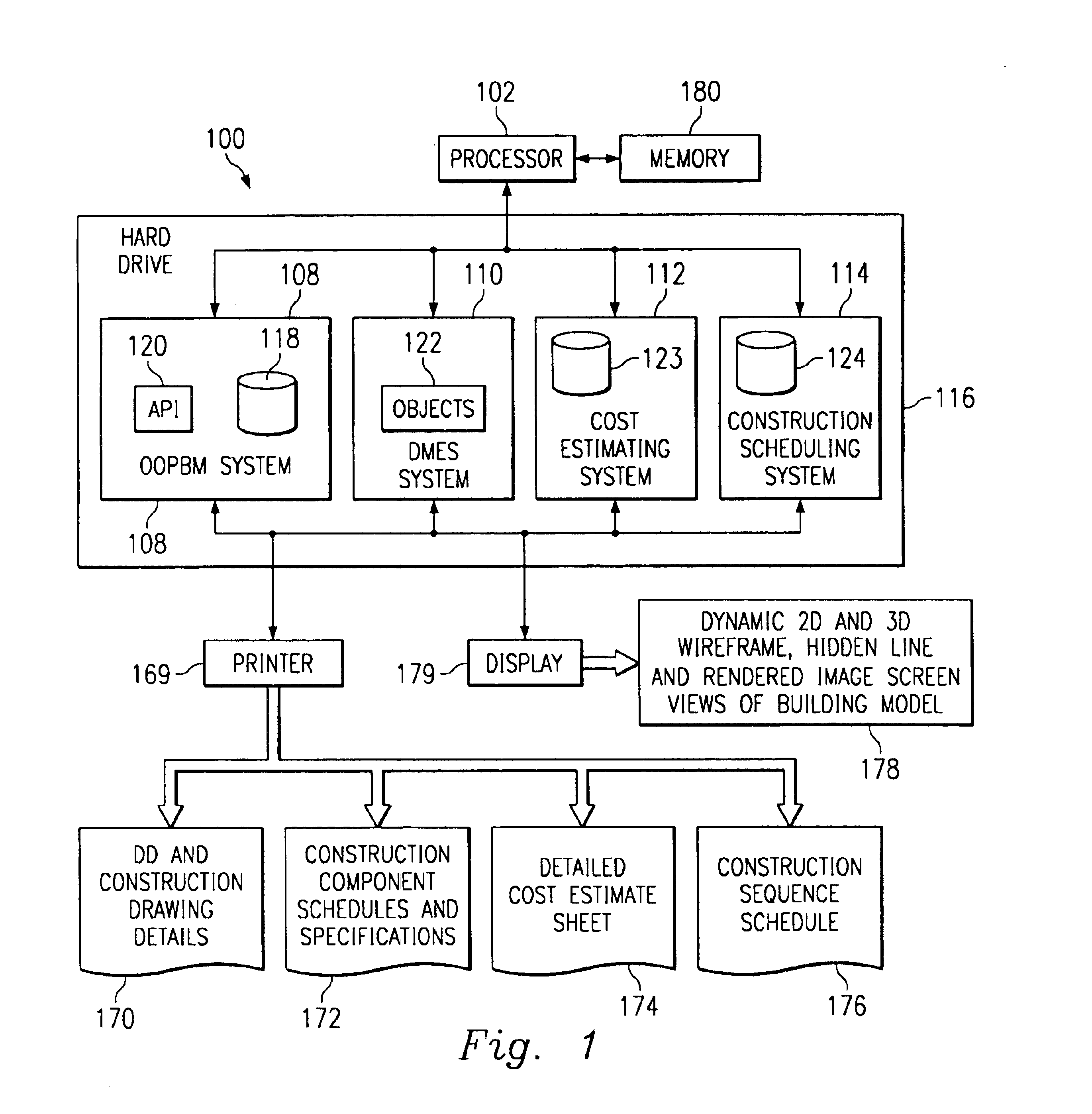
[0053]FIG. 1 illus...


PUM


Abstract

A computer-implemented automated building design and modeling and construction project cost estimating and scheduling system (“DMES system”) is described. The DMES system provides a central source for all of the design and construction information for a construction project in a coordinated two-dimensional and three-dimensional spatial database that is freely accessible by all of the members of an interdisciplinary construction project team as a means to produce automatically coordinated design development and construction document information. The DMES system acquires and stores all of the appropriate design, engineering, and construction expertise and information available for any building type for use in automatically assembling and coordinating the design, cost-estimating, and scheduling for a construction project. In one embodiment, the DMES system consists of a plurality of objects, comprising elements and massing elements arranged in an assembly hierarchy. Each of the objects includes programming code that defines an interface and discrete internal functions that define its behavior. When instantiated in the database, the objects automatically create further instances of other objects in the hierarchy, which in turn do the same, thus assembling a complete building model automatically from the initial manually-placed instance. The building model enables automatic generation of drawings and cost and scheduling information. By running automatic iterations of the building model, multiple designs may be evaluated to determine the optimum design.

Description

BACKGROUND OF THE INVENTION[0002]This invention relates generally to computer-aided design of buildings and, more particularly, to a system for enabling the computer-aided development of a design for a building, along with design development drawings, specifications, and cost and scheduling data associated with the design.[0003]Demands for more expedient, more accurate design, cost, and schedule responses to clients' requests for new building and renovation work prompted the development of the invention described herein. Traditionally, architects, engineers, and contractors (the “AEC Industry”) are pressured to respond ever more quickly to clients' requests for building designs, cost estimates, and construction schedules in connection with construction projects. In addition to needing to respond promptly to their clients requests for information and data, AEC Industry companies need to insure that such information and data is accurate. To remain competitive in today's marketplace, A...

Claims


Application Information

Patent Timeline
Patent Type & Authority Patents(United States)
IPC IPC(8): G06Q10/00G06Q10/06G06Q30/06G06Q50/08
CPCG06F17/5004G06F17/5086G06Q50/08G06Q30/0603G06Q10/06G06F30/13G06F30/17
Inventor WAKELAM, ROBERT BRUCEBECK, III, HENRY C. PETERPHILLIPS, BRADLEY PAULPOWELL, GREGORY WAYNEO'KELLY, NIALL BRENDAN
Owner BECK TECH
Why Eureka
Try Eureka