Gear transmission assembly for electrical power tool

Active Publication Date: 2005-03-01
HILTI AG
View PDF8 Cites 65 Cited by
  • Summary
  • Abstract
  • Description
  • Claims
  • Application Information

AI Technical Summary

Benefits of technology

The shifting slide advantageously has at least one opening for receiving the shifting part which insures a compact structure. The opening can be easily formed and its facilitates the assembly of the gear transmission assembly.
The at least one opening extends transverse to a longitudinal axis of the gear train and substantially tangentially to the indexing gears. This insures a simple assembly and a reliable guidance of the shifting parts in the shifting slide.
Ad

Problems solved by technology

A drawback of the known gear transmission assembly consists in that for a

Method used


Image

  • Gear transmission assembly for electrical power tool
  • Gear transmission assembly for electrical power tool
  • Gear transmission assembly for electrical power tool

Examples


Example

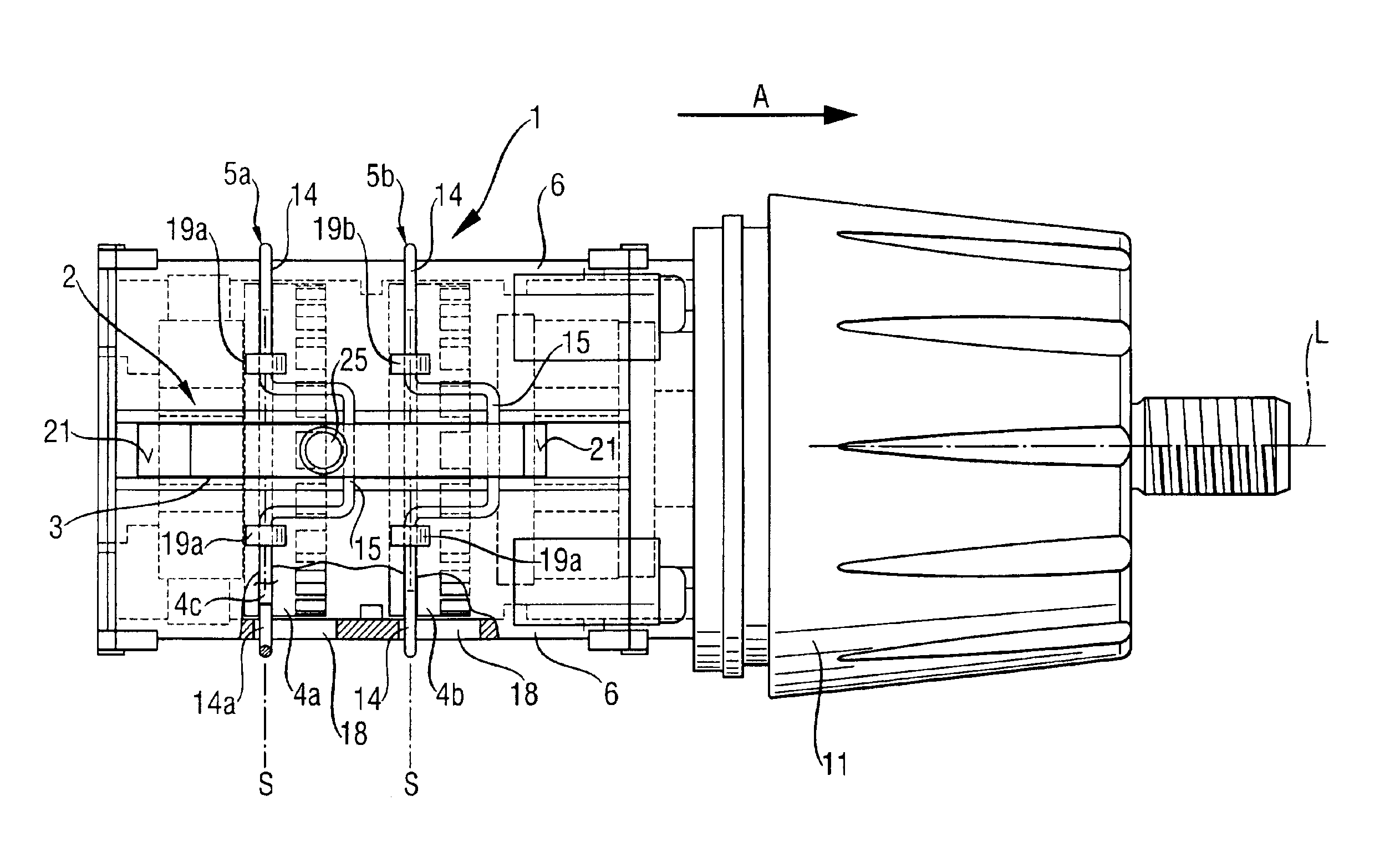
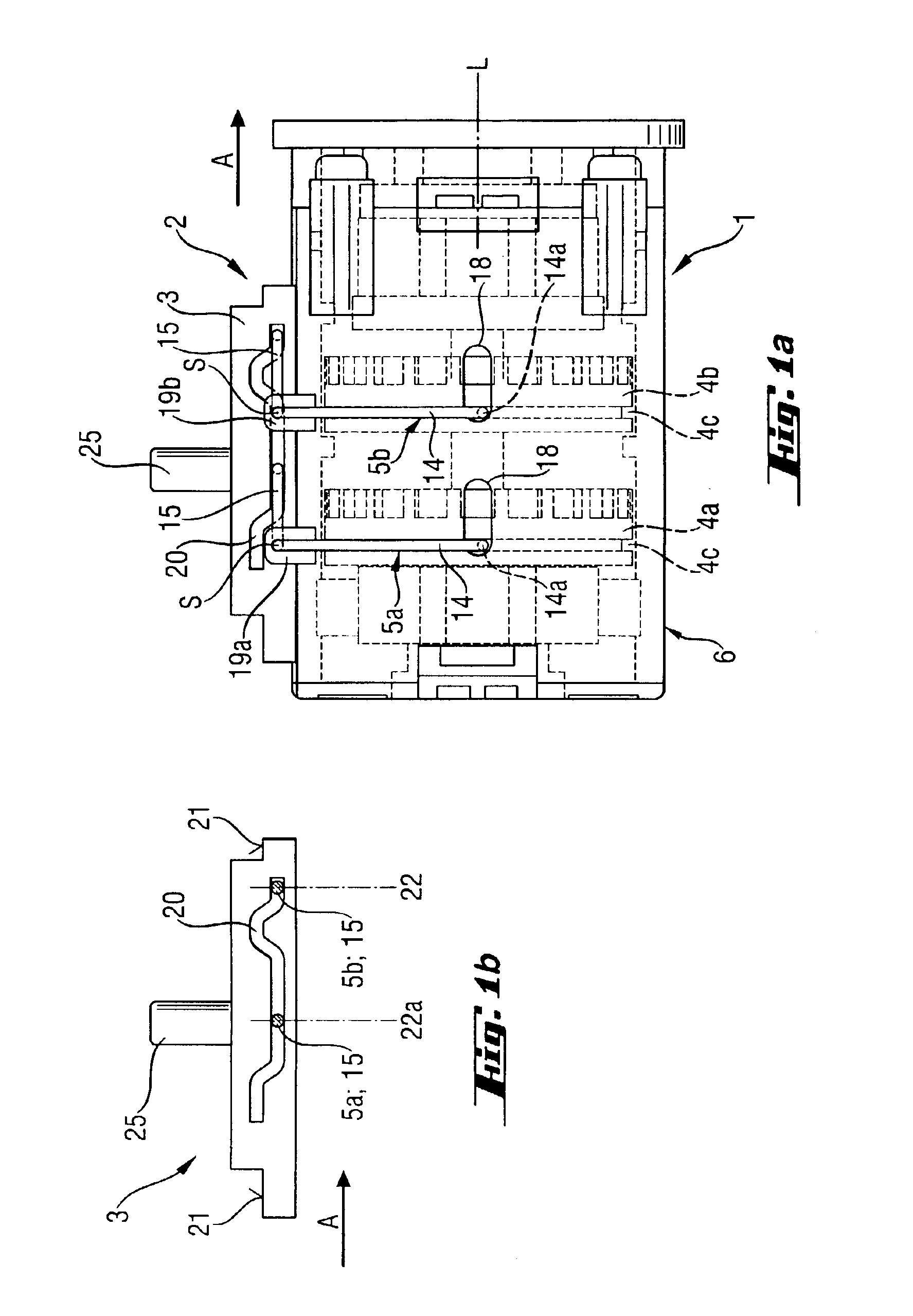
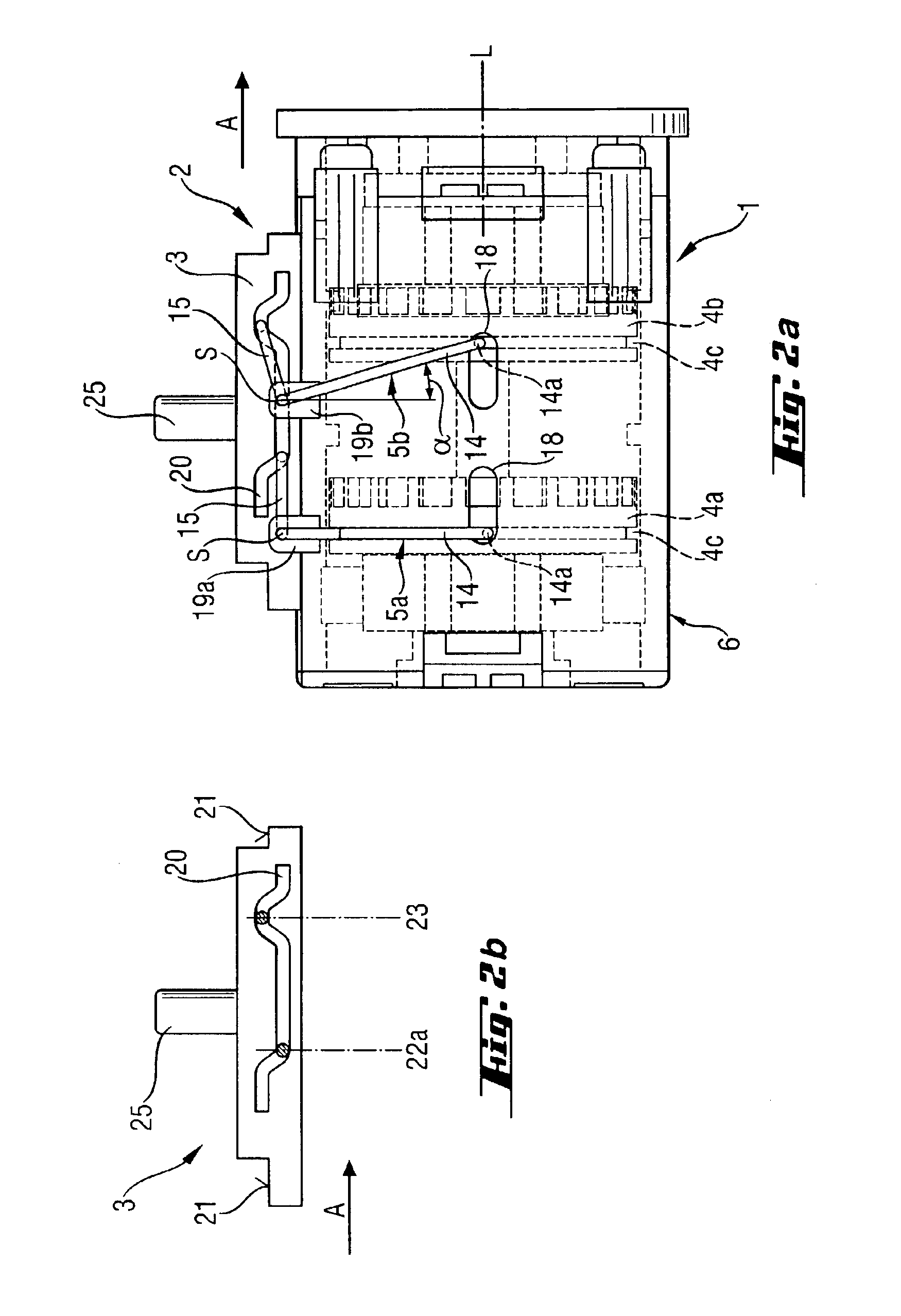
FIGS. 1 through 7 shown a gear train 1 of a gear transmission assembly according to the present invention of an electrical tool which is adjoined in the operational direction A by a chuck (FIG. 4) for receiving a tool holder, e.g., of a screw bit. The gear train 1 is located in a substantially cylindrical housing 6 formed, e.g., of a plastic material and the like. The inventive gear transmission assembly further includes a shift mechanism 2 for shifting the gear train 1 from one stage to another. The shift mechanism 2 includes a spring-biased shifting slide 3 displaceable between three shift stages shown in particular in FIGS. 1a, 2a, 3a, and first and second shifting stirrups 5a and 5b which act on respective, axially displaceable indexing gears 4a, 4b.

FIG. 5 shows a U-shaped shifting stirrup 5a, 5b having a shifting part 15 and two engagement parts 14 which form free ends 14a of the shifting stirrup 5a, 5b, with the shifting part 15 connecting the two engagement parts 14a with ea...


PUM


Abstract

A gear transmission assembly for an electrical power tool includes a housing (6), a multi-stage gear train (1) located in the housing and having a plurality of axially displaceable indexing gears (4a, 4b) associated with respective stages of the gear train (1) and a shift device (2) for shifting the gear train (1) from one stage to another and having a shifting slide (3) displaceable from one shift stage to another, and a plurality of springable shifting stirrups (5a, 5b) connected with the shifting slide (3) and cooperating with respective indexing gears (4a, 4b) for displacing same in response to displacement of the shifting slide (3) between shift stages.

Description

BACKGROUND OF THE INVENTION1. Field of the InventionThe present invention relates to a gear transmission assembly for an electrical power tool and including a two-stage gear train located in the housing and having an axially displaceable indexing gear, and a shift device for shifting the gear train from one stage to another and having a shifting slide displaceable from one shift stage to another, and a springable shifting stirrup connected with the shifting slide and cooperating with the indexing gear for displacing same in response to displacement of the shifting slide between shift stages.2. Description of the Prior ArtGear transmission assemblies of the type described above are used in electrical power tools in order to adapt a rotational speed of a power tool and, thus, of a used working tool, e.g., a screw bit, drill, etc. . . . to prevailing condition.German Publication DE 3 904 085 discloses a gear transmission assembly for an electrical power tool and including a multi-stage...

Claims


Application Information

Patent Timeline
IPC IPC(8): B25F5/00
CPCB25F5/001
Inventor SPIELMANN, DAVIDGERSCHWILER, OTHMARBREITENMOSER, ARMINLAUBE, CHRISTIAN
Owner HILTI AG
Why Eureka
Try Eureka