Hollow fiber membrane for the degassing of inks, ink degassing method, ink degassing apparatus, method for the fabrication of an ink cartridge, and ink

a technology of ink degassing and fiber membrane, which is applied in the direction of liquid degasification, membranes, separation processes, etc., can solve the problems of insufficient degassing, ink may be deteriorated, and print dot loss, and achieve the effect of efficient degassing

Inactive Publication Date: 2005-03-01
MITSUBISHI CHEM CORP
View PDF13 Cites 19 Cited by
  • Summary
  • Abstract
  • Description
  • Claims
  • Application Information

AI Technical Summary

Benefits of technology

The present invention has been made in view of the above-described disadvantages, and an object thereof is to provide a hollow fiber membrane for the degassing of inks which, when used to remove dissolved gases from an ink, permits the ink to be efficiently degassed with a slight pressure loss in the ink flow path and without any damage to the hollow fiber membrane upon exposure to pressure changes, an ink degassing method, and an ink degassing apparatus.
Another object of the present invention is to provide a method for the fabrication of an ink cartridge for use in ink-jet printers wherein the dissolved gas concentrations in the ink are very low.

Problems solved by technology

Moreover, it is also known that, when the ink head is repeatedly pressurized and depressurized during ink ejection, dissolved gases (e.g., dissolved oxygen and dissolved nitrogen) present in the ink tend to stagnate in the ink head and cause print dot losses at the time of ink ejection.
However, physical methods are disadvantageous, for example, in that the degree of degassing is insufficient or the ink may be deteriorated.
Moreover, chemical methods are also disadvantageous, for example, in that the dye contained in the ink may undergo a chemical change.
This causes a considerable pressure loss in the hollow fibers and hence requires high mechanical strength for the whole system, resulting in an increased cost.
This is disadvantageous in that, when the outer surface side of the hollow fibers is evacuated by starting a vacuum pump or returned to atmospheric pressure, the hollow fibers tend to vibrate and suffer damage as a result of mutual contact.
However, the surface of the porous base material is gradually made hydrophilic by the hydrophilic compound, so that the ink may undesirably leak out through the pores of the membrane.
Consequently, when the hollow fiber membrane has a membrane thickness ensuring adequate mechanical strength, it is difficult to obtain a sufficient gas permeability.
As a result, the dissolved gas concentration in the degassed ink has been limited to as high as 6.4 ppm or so.

Method used


Image

  • Hollow fiber membrane for the degassing of inks, ink degassing method, ink degassing apparatus, method for the fabrication of an ink cartridge, and ink
  • Hollow fiber membrane for the degassing of inks, ink degassing method, ink degassing apparatus, method for the fabrication of an ink cartridge, and ink
  • Hollow fiber membrane for the degassing of inks, ink degassing method, ink degassing apparatus, method for the fabrication of an ink cartridge, and ink

Examples


example 1

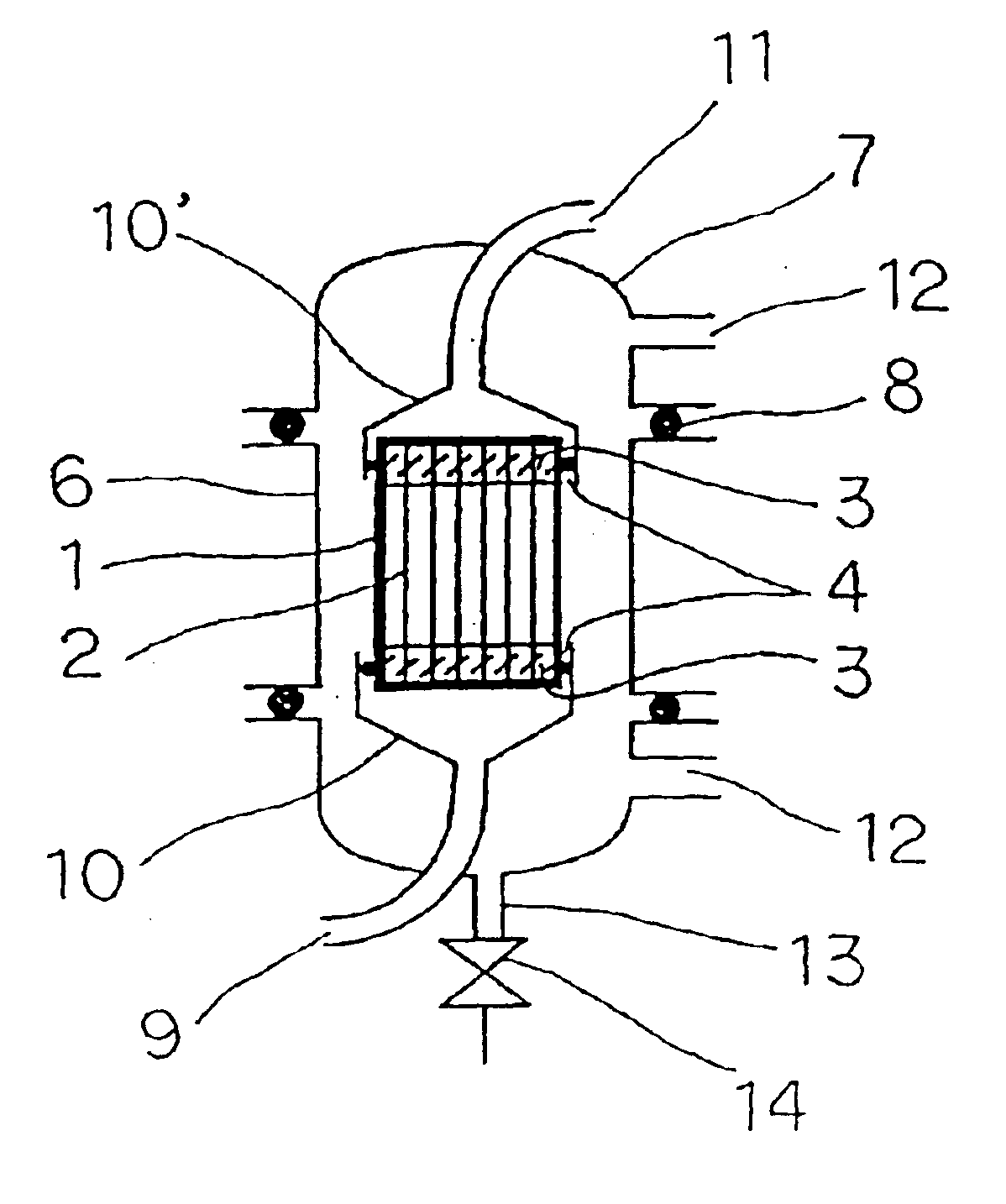
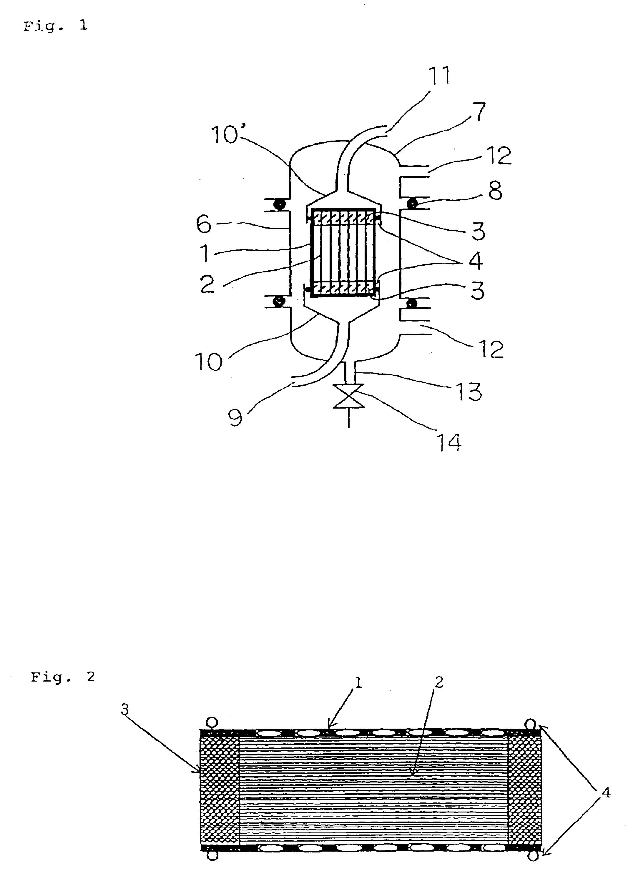
A composite hollow fiber membrane having an inner diameter of 200 μm and a membrane thickness of 40 μm and consisting of a nonporous layer formed of a segmented polyurethane [Tecoflex EG80A (trade name), manufactured by Thermedix Co., Ltd.; MRF=15; density=1.04] and porous layers formed of high-density polyethylene [Hizex 2200J (trade name), manufactured by Mitsui Chemical Co., Ltd.; MRF=5.2; density=0.968] and disposed on both sides of the nonporous layer was provided. The thickness of the nonporous layer was 0.8 μm and the pore diameter of the porous layer was 0.1 μm. This composite hollow fiber membrane had an oxygen permeation flux of 7.7×10⁻⁹ cm3 / (cm2·Pa·sec) and a nitrogen permeation flux of 3.0×10⁻⁹ cm3 / (cm2·Pa·sec). In a perforated cylindrical case made of a modified PPO resin, a large number of hollow fibers comprising this hollow fiber membrane were bundled and fastened together with fastening members comprising an epoxy resin so that both ends of the hollow fibers were le...

example 2

A hollow fiber membrane element having the same construction as that of Example 1, except that the effective hollow fiber length was 60 cm, was fabricated. This hollow fiber membrane element was installed in a canister and used to degas an ink under the same conditions as in Example 1.

Before the degassing treatment, the dissolved gas concentrations in the ink were 13.9 mg / L for nitrogen and 8.3 mg / L for oxygen. As a result of this treatment, the dissolved nitrogen and oxygen concentrations were reduced to 2,330 μg / L and 280 μg / L, respectively.

example 3

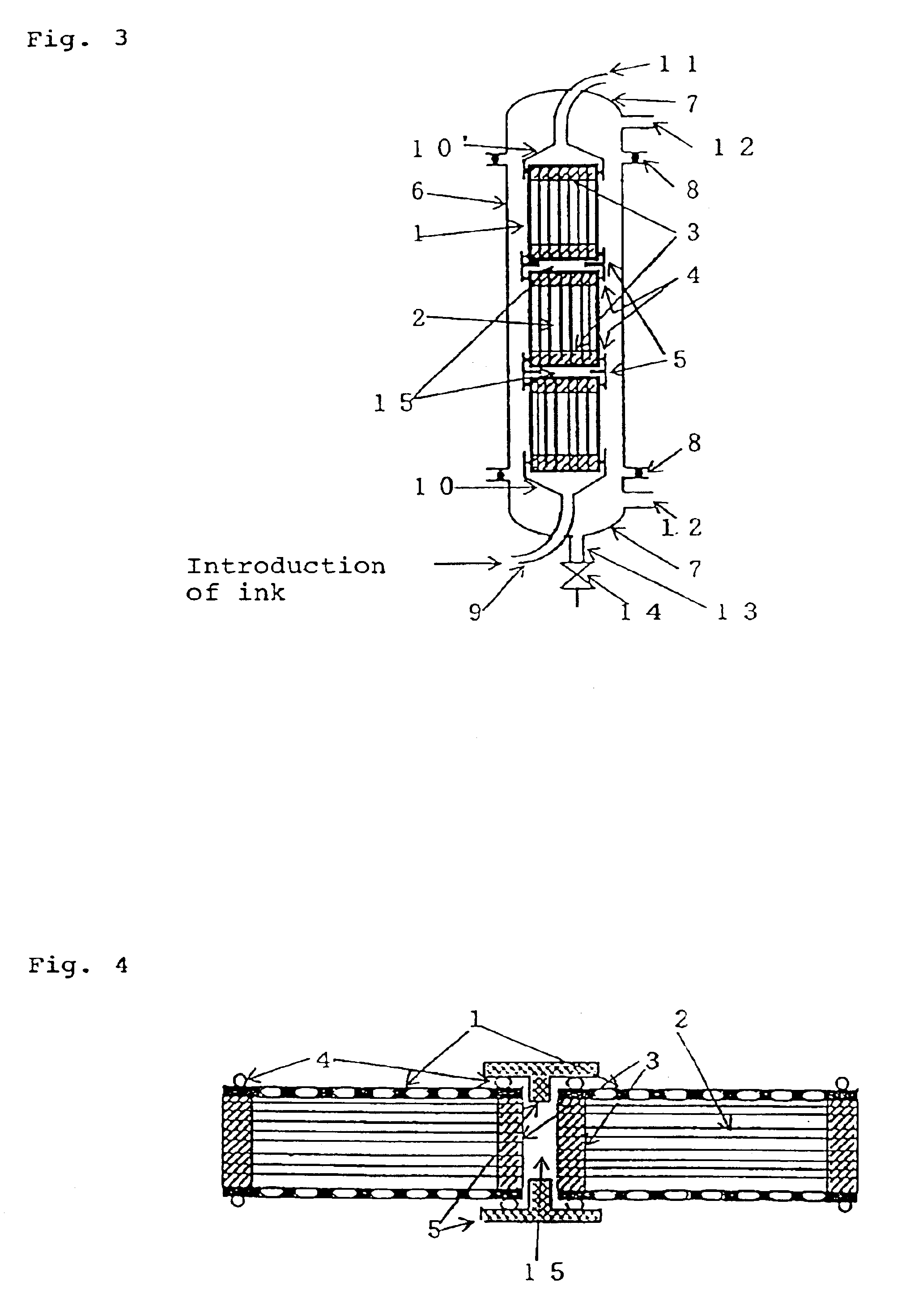
Three hollow fiber membrane elements similar to that fabricated in Example 1 were connected in series by means of connectors as illustrated in FIG. 4. The connected hollow fiber membrane elements were installed in a canister as illustrated in FIG. 3, and used to degas an ink under the same conditions as in Example 1.

Before the degassing treatment, the dissolved gas concentrations in the ink were 14.1 mg / L for nitrogen and 8.2 mg / L for oxygen. As a result of this treatment, the dissolved nitrogen and oxygen concentrations were reduced to 1,800 μg / L and 95 μg / L, respectively.


PUM

PropertyMeasurementUnit
thicknessaaaaaaaaaa
inner diameteraaaaaaaaaa

Abstract

The present invention provides a gas-permeable hollow fiber membrane having an inner diameter of 50 to 500 μm and a membrane thickness of 10 to 150 μm, which is preferably a composite hollow fiber membrane having a three-layer structure consisting of a nonporous layer having porous layers disposed on both sides thereof. Dissolved gases present in an ink can be removed by passing the ink through the bores of hollow fibers comprising such a hollow fiber membrane, and evacuating the outer surface side of the hollow fibers. This method makes it possible not only to degas inks with a slight pressure loss, but also to degas inks stably even if pressure changes occur during degassing.

Description

TECHNICAL FIELDThis invention relates to a hollow fiber membrane for the degassing of inks which can be used to remove dissolved gases from inks for use in ink-jet printers and the like, an ink degassing method, and an ink degassing apparatus, as well as a method for the fabrication of an ink cartridge by using the same.BACKGROUND ARTIn ink-jet printers, an ink is delivered from an ink cartridge to a printer head by capillary action. However, it is known that, during delivery of the ink, minute air bubbles present in the ink or within the ink cartridge gives flow resistance to the ink. Moreover, it is also known that, when the ink head is repeatedly pressurized and depressurized during ink ejection, dissolved gases (e.g., dissolved oxygen and dissolved nitrogen) present in the ink tend to stagnate in the ink head and cause print dot losses at the time of ink ejection.Methods for removing dissolved gases from an ink are roughly classified into physical methods for degassing an ink by...

Claims


Application Information

Patent Timeline
Patent Type & Authority Patents(United States)
IPC IPC(8): B01D61/00B01D63/04B01D63/02B01D69/02B01D69/00B01D69/08B01D19/00B41J2/17B41J2/19
CPCB01D19/0031B01D61/00B01D63/02B01D69/02B01D69/08B41J2/19B01D63/043B01D2313/13
Inventor WATARI, KENJITAKEDA, SATOSHIKOBAYASHI, MASUMIUCHIDA, MAKOTOUENISHI, MASAMOTOFUKUSHIMA, NORIAKIHAYASHI, SEIJI
Owner MITSUBISHI CHEM CORP
Why Eureka
Try Eureka