Hierarchical telecommunications network with fault recovery

Inactive Publication Date: 2005-03-01
RED HAT
View PDF4 Cites 88 Cited by
  • Summary
  • Abstract
  • Description
  • Claims
  • Application Information

AI Technical Summary

Benefits of technology

Recovery is decentralized, as recovery decisions are made at the L2 nodes near the error condition, rather than at a central controller. Recovery is thus fa

Problems solved by technology

High granularity traffic is collected, routed and manipulated at L2 nodes but generally passes

Method used


Image

  • Hierarchical telecommunications network with fault recovery
  • Hierarchical telecommunications network with fault recovery
  • Hierarchical telecommunications network with fault recovery

Examples


Example

Overview

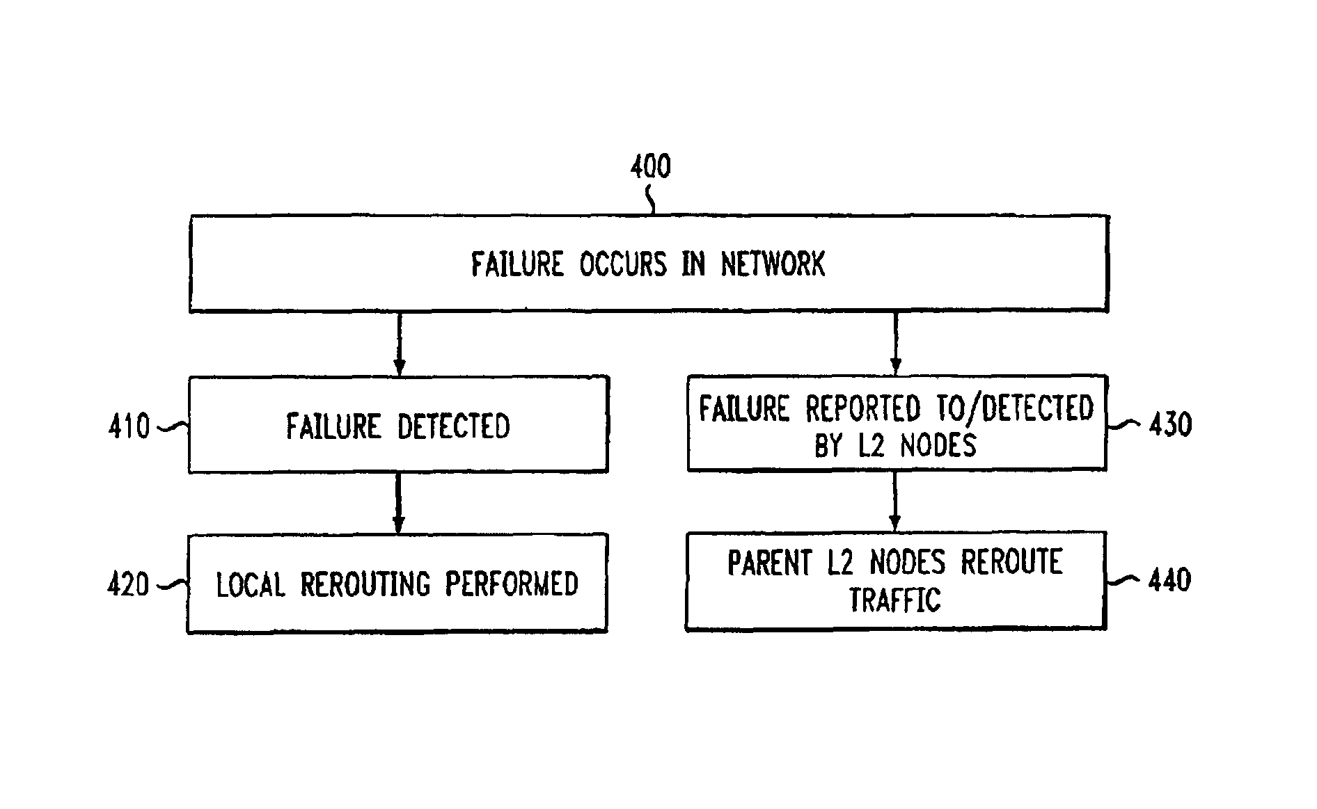
The present invention is directed to a hierarchical communications network allowing for fast network recovery while making efficient use of network components. An exemplary embodiment of the present invention divides network nodes into two categories (levels), where high-level nodes (“L2” nodes), a minority of the nodes, are primarily responsible for error recovery, and low-level nodes (“L1” nodes) perform minimal error recovery operations. High-level nodes generally have the capacity to perform routing on traffic at high levels of granularity; low-level nodes generally allow such high granularity traffic to pass through the nodes without any routing or manipulation. This architecture allows for recovery from network errors (e.g., the failure of a link) and routing in general to be performed more quickly, using less equipment and without centralized coordination.

In an exemplary embodiment, recovery equipment is concentrated in a small set of nodes (L2 nodes), lowering the am...


PUM


Abstract

The present invention is a telecommunications network having a hierarchical architecture which reduces the amount of equipment and processing required to recover from network failures. In an exemplary embodiment, the nodes of the network are divided into high level nodes and low level nodes. High granularity traffic is collected, routed and manipulated at high level nodes, but generally passes through low level nodes, which generally lack the capability for routing and manipulating such high granularity traffic. Equipment savings results from low level nodes lacking the capability to manipulate traffic other than traffic relevant to those nodes or nearby nodes. Each high level node pair is connected by at least three node disjoint paths of low level nodes and links. Less protection capacity is needed, as each node disjoint path is expected to handle only a portion of rerouted traffic in the event of a network equipment failure. Recovery is decentralized, and is thus faster, requires less equipment, and is less susceptible to the failure of a centralized controller than with networks using centralized recovery processing.

Description

BACKGROUND OF THE INVENTIONThis invention relates to telecommunications networks. More particularly, this invention relates to an improved network architecture for more effectively and efficiently recovering from failures.A telecommunications network transports information from a source to a destination. The source and destination may be in close proximity, such as in an office environment, or thousands of miles apart, such as in a long-distance telephone system. The information, which may be, for example, computer data, voice transmissions, or video programming, is known as traffic, usually enters and leaves a network at nodes, and is transported through the network via links and nodes. The overall traffic comprises multiple data streams which may be combined in various ways and sent on common links. Generally, a data stream is a flow of data or information and may comprise multiple component data streams.Nodes, sometimes termed offices, are devices or structures that direct traffi...

Claims


Application Information

Patent Timeline
IPC IPC(8): H04L12/24
CPCH04L41/0663
Inventor SIMMONS, JANE MARIE
Owner RED HAT
Why Eureka
Try Eureka