Flush panel spacer and method and apparatus of installing the same

a technology of flush panels and spacers, which is applied in the field of spacers, can solve the problems of inability to meet localized concentrated loading forces, aluminum alloys, alloy steels are frequently not compatible with graphite, and the panel does not have significant transverse reinforcement, etc., to facilitate automatic installation of spacers

Inactive Publication Date: 2005-03-08
SPS TECH LLC
View PDF16 Cites 62 Cited by
  • Summary
  • Abstract
  • Description
  • Claims
  • Application Information

AI Technical Summary

Benefits of technology

The present invention provides an improved spacer and / or fastener that can be mounted within a panel, such as a composite or sandwich structure panel of a predetermined thickness with a drilled hole to provide a flush mounting of an upper edge of an upper rim member of the spacer with an upper face surface of the panel. A spacer can include a body member having a central aperture with a larger lower flange member that extends radially outward from the body member. The flange member will bear against the lower face surface of the sandwich structure panel. An adhesive can be applied between the lower flange member and the lower face surface of the panel to assist in securing the spacer to the panel. The upper rim member extends upward from the body member and is concentric with the central aperture. The rim member has a larger inner diameter, than the diameter of the central aperture, with an inner flange extending from the rim member to the central aperture. The spacer will be sized for a particular panel thickness, such that the upper edge of the upper rim member will initially be extended above the upper panel surface when the lower flange member is in contact with the lower panel surface by a predetermined distance.
The sealing compound is thus applied automatically to the hole in the sandwich panel with the spacer being the carrier of the sealing compound. This facilitates an automatic installation of spacers in the aerospace industry.

Problems solved by technology

However, such fiber-reinforced composite panels do not necessarily respond well to localized concentrated loading forces.
Some of the problems that have been recognized in the installation of a spacer are the necessary chemical compatibility of any fastener or spacer used in sandwich panels so that there is not any galvanic corrosion.
This issue frequently arises when the sandwich panels contain carbon fiber, and if the fibers come in contact with a less noble metallic fastener, there can be corrosion, thus, magnesium, aluminum, aluminum alloys, and alloy steels are frequently not compatible with a graphite based structure.
Another problem that has occurred with mounting fasteners and spacers in a sandwich panel is that the panel does not have a significant transverse reinforcement.
Thus, when a hole is drilled for mounting a spacer, the edge of the hole can be crushed, since there is relatively little resistance to a crushing force.
As can be appreciated, the application of a fastener or spacer to a sandwich panel can damage the panel in drilling holes in the panels in that surface ply splintering, surface ply delaminating, heat damage, and irregularities inside the hole can occur.
When composite panels are drilled or machined, the natural sealing process of lamination is disrupted.
If the sandwich panels have an aluminum face sheet, the liquid can leak into the interior core of the panel.
These leakage problems can result in weight gain, laminate degradation, and even unpleasant odors.
Any protrusions above the upper surface can be abraded and can further cause carpet wear.
Thus, the prior art is still attempting to optimize the design of spacers and fasteners used in sandwich panels in aircraft and the problems of sealing with a flush installation of spacers with a surface of a panel has yet to be optimized.

Method used


Image

  • Flush panel spacer and method and apparatus of installing the same
  • Flush panel spacer and method and apparatus of installing the same
  • Flush panel spacer and method and apparatus of installing the same

Examples


Embodiment Construction

The following description is provided to enable any person skilled in the art to make and use the invention and sets forth the best modes contemplated by the inventors of carrying out their invention. Various modifications, however, will remain readily apparent to those skilled in the aerospace art, since the general principles of the present invention have been defined herein specifically to provide an improved panel spacer and method and apparatus of installing the same, for example in a floor panel of an aircraft.

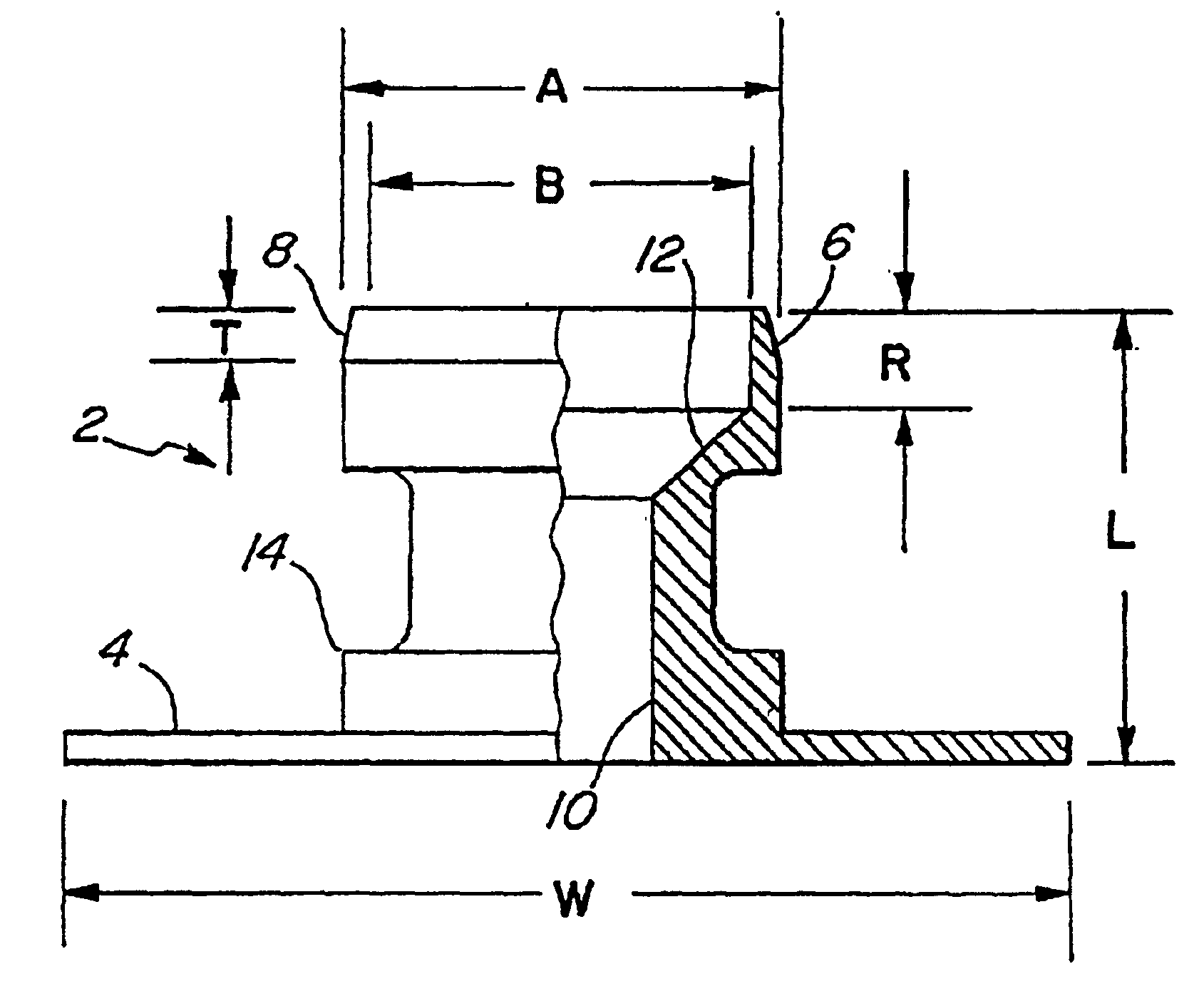
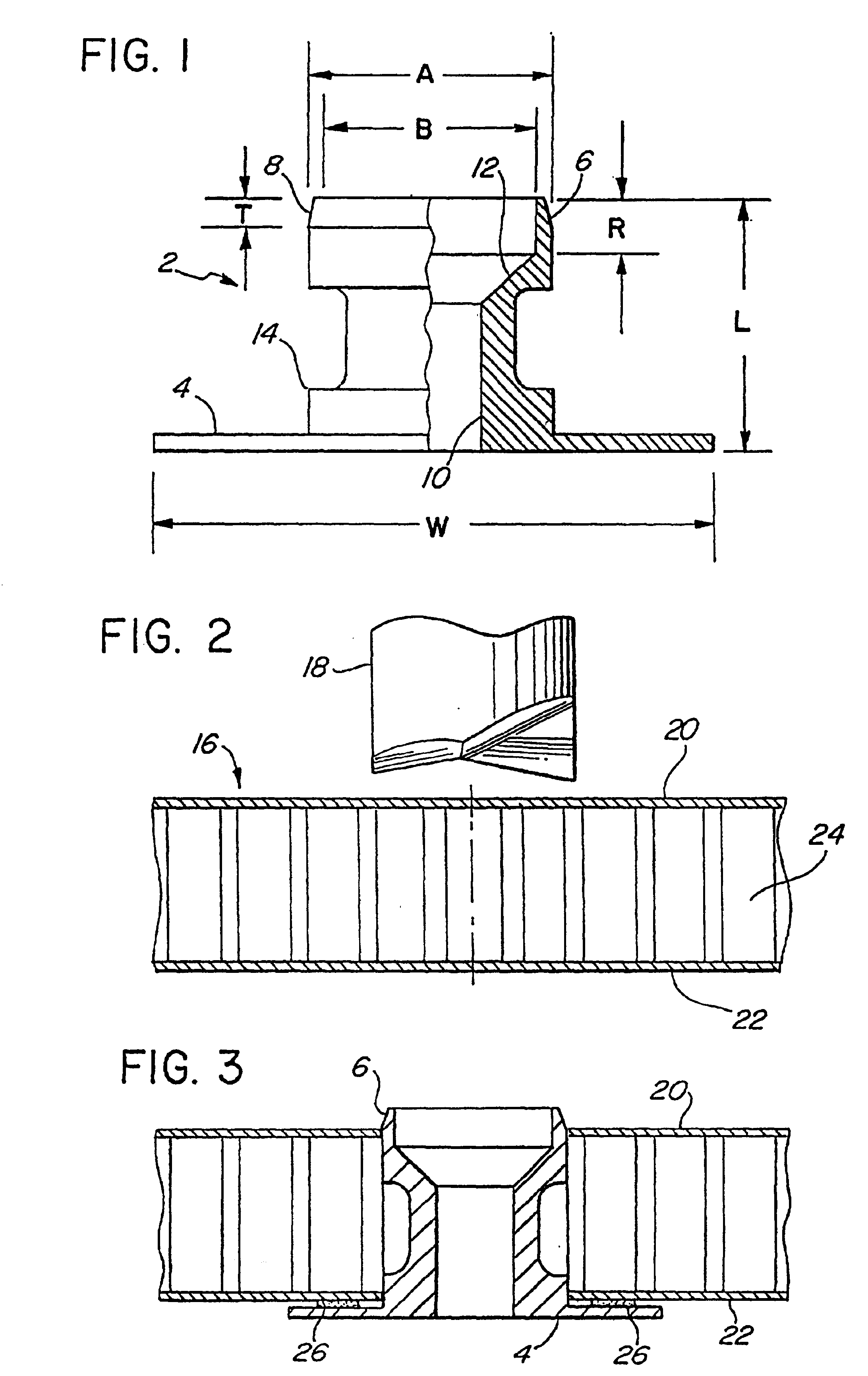
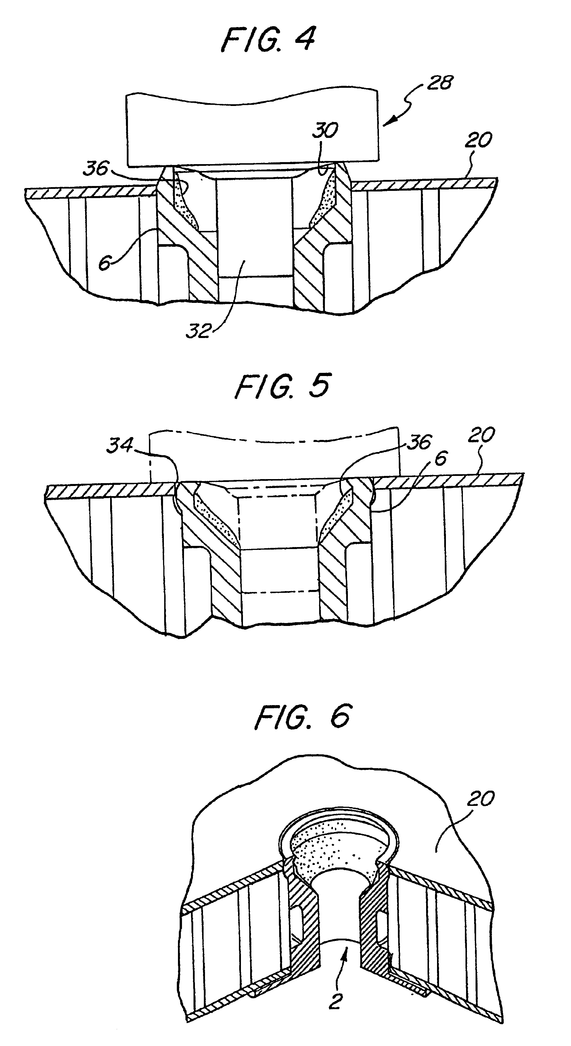
A spacer of the present invention is disclosed in FIG. 1. The spacers of the present invention can be broadly described as inclusive of panel inserts that are to be mounted in a sandwich panel structure where an upper edge of a rim is deformed to provide an edge which is flush with the perimeter of the hole. The spacer can have a smooth central bore whereby a fastener will extend through the bore for mounting with a nut or clip nut. Alternatively, the spacer can have a t...


PUM

PropertyMeasurementUnit
thicknessaaaaaaaaaa
thicknessaaaaaaaaaa
heightaaaaaaaaaa

Abstract

A method of installing an insert in a sandwich panel for mounting a fastener includes making a hole in the panel and inserting a spacer having a height greater than the thickness of the panel. An entrance rim of the spacer extends above an upper surface of the panel and a setting tool exerts a force on the entrance rim to force it into the hole and to position an upper edge of the entrance rim flush with the panel surface. The spacer can include an annular groove on an interior wall of the entrance rim to facilitate the cold working deformation during an installation in the panel and a hole engaging surface to align and maintain the spacer within the hole. An outer exterior surface of the entrance rim can be indented and coated with a first sealing compound to ensure a watertight seal with the panel. A second sealant material can be provided within the entrance rim for sealing with a head of any fastener extending through the spacer. An improved floor panel with spacer is accordingly provided for aircraft.

Description

BACKGROUND OF THE INVENTION1. Field of the InventionThe present invention is directed to spacers for mounting fasteners in sandwich panels, a method of installing the spacers so that the spacers are flush with an upper surface of the panels and can provide a liquid tight seal and a resultant improved panel assembly, such as a floor of an aircraft.2. Description of Related ArtIn the aerospace field a premium is placed upon light-weight but strong structural components. For example, a floor of an aircraft must be lightweight and strong and also must accommodate the stresses imposed upon the bulkhead by the flexing of the wings during flight. The aircraft industry uses sandwich panels that are fastened to spars and bulkheads by a large number of fasteners that are secured to the panels by extending through corresponding spacers mounted in the panels. Frequently, the sandwich panels are formed of thin aluminum face plates with expandable aluminum foil strips to form a core or laminated ...

Claims


Application Information

Patent Timeline
Patent Type & Authority Patents(United States)
IPC IPC(8): F16B5/00F16B5/01B21D39/00E04C2/30
CPCF16B5/01
Inventor MCCORKLE, DANIEL J.WAITS, BOBBY L.SECRETS, PAUL M.RIVERON, JR., FAUSTINO
Owner SPS TECH LLC
Why Eureka
Try Eureka