
Device and methods for dressing card clothing

a card clothing and dressing technology, applied in the field of card clothing dressing devices, can solve the problems of grievous injuries, still entail a great deal of risk, and is not possible, and achieve the effect of fast and inexpensive maintenance work on card clothing

Inactive Publication Date: 2005-03-08
GRAF CIE AG
View PDF12 Cites 13 Cited by
  • Summary
  • Abstract
  • Description
  • Claims
  • Application Information

AI Technical Summary

Benefits of technology

In view of the problems described above with respect to state-of-the-art devices, the object of the present invention is to develop devices of the type specified at the beginning, with which maintenance work on card clothing can be performed especially fast and inexpensively. A further object is to provide methods that can be used with devices of this type.
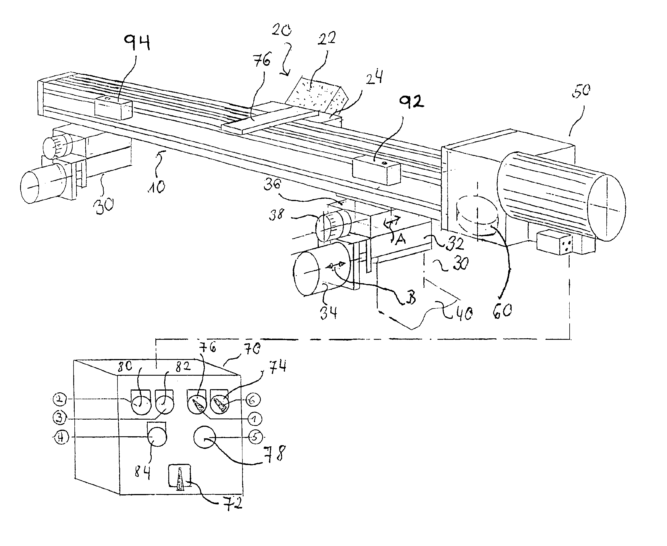
In accordance with the invention, on the other hand, it is possible to release dressing elements of the dressing system from a safe distance and press them against the clothing to be dressed by advancing the dressing elements towards the clothing with the remote-controlled advancing mechanism. This makes it possible to dress individual, separate segments of the clothing in the center of the cylindrical drum and thus to achieve a significant reduction of the dressing time in cases of local wear and / or local fouling. More importantly, however, this device also makes it possible to perform all necessary dressing of the clothing without endangering the maintenance personnel, because now they merely have to operate the remote control for the advancing mechanism during the rotation of the clothing drum. Especially in view of the acceleration of the maintenance work, it was found that the additional expense of providing remote-controlled advancing mechanisms is quite acceptable, so that overall the maintenance work can be performed especially inexpensively with the device of the invention.
From the standpoint of design and installation, it was found to be especially advantageous, if the advancing mechanism for advancing the dressing element by remote control can be operated together with the support beam, the slide, and / or the guide element. In this embodiment of the invention, the advancing mechanism can move the entire device consisting of the guide element and the dressing system towards the clothing. Therefore, to advance the dressing element, it is not necessary to use drive elements that can be moved along the predetermined path, but rather advancing elements arranged at a predetermined place on the predetermined path can be used to effect the required advancing movement. The design and installation of the device of the invention are simplified in this way.
Although the advancing system of a device of the invention may also have a remote-controlled electric motor, to achieve especially good operational reliability, it was found to be advantageous, if the advancing system has a preferably double-acting pneumatic lifting cylinder, which is connected by suitable fluid lines with a control device that allows remote control of the lifting cylinder.
In this regard, by providing a coupling system for the releasable connection of the dressing system to the drive mechanism, it is possible to prevent damage to the drive mechanism during maintenance work, in the course of which a dressing element is automatically carried along by clothing helically arranged on the cylindrical drum. In this embodiment of the invention, the drive mechanism can first move the dressing system along the predetermined path to a starting point of the desired dressing operation. The dressing system is then uncoupled from the drive mechanism. It is then advanced towards the clothing by the remote-controlled advancing mechanism and automatically moved by the clothing helically arranged on the drum over the area to be dressed. The dressing element can then be pulled away from the clothing, and the dressing system can be recoupled to the drive mechanism to be moved to the next area to be dressed. To achieve fully automatic control of a device of the invention, at least one switching element located on the dressing system and / or the guide element can be assigned to the control device. The operation of this switching element can initiate a change in the movement of the dressing system along the predetermined path, or it can initiate an advancing movement and / or a movement in the opposite direction from the advancing direction. In this embodiment of the invention, after examination of the clothing to be dressed, the switching elements are positioned in the area of the clothing segments that are to be subjected to dressing.
As is evident from the above explanation, a method in accordance with the invention for dressing a card clothing with a device of the invention is essentially characterized by the fact that the dressing system is moved along the predetermined path to a starting point of the dressing and then advanced towards the clothing by remote control. In this regard, when the dressing system reaches an end point of the predetermined path, it can be pulled away from the clothing in the opposite direction from the advancing direction. When the dressing system reaches the starting point, it can be uncoupled from the drive mechanism, and / or when it reaches the end point, it can be coupled to the drive mechanism. It is advantageous to establish the starting point and the end point by appropriate positioning of suitable switching elements.

Problems solved by technology

On the other hand, in many cases it is not possible, for safety reasons, to operate the previously known devices of the type described above only in portions of the clothing.
This is true especially of the grinding devices described above, because it is unsafe to release the grinding stone manually in the center of the carding element, such as the swift of a card, so that it is pressed against the clothing by the pretensioning device.
This problem is especially evident in modern high-speed cards or carding machines, in which the clothing is drawn over a drum with a diameter of up to 2 m and a length of several meters.
If the maintenance person comes within range of the clothing, grievous injuries may result.
For this reason, maintenance work performed with the previously known devices is usually performed over the entire axial length of the clothing, so that the dressing elements can be released at the edge of the clothing, which, however, still entails a great deal of risk.

Method used


Image

  • Device and methods for dressing card clothing
  • Device and methods for dressing card clothing

Examples


Embodiment Construction

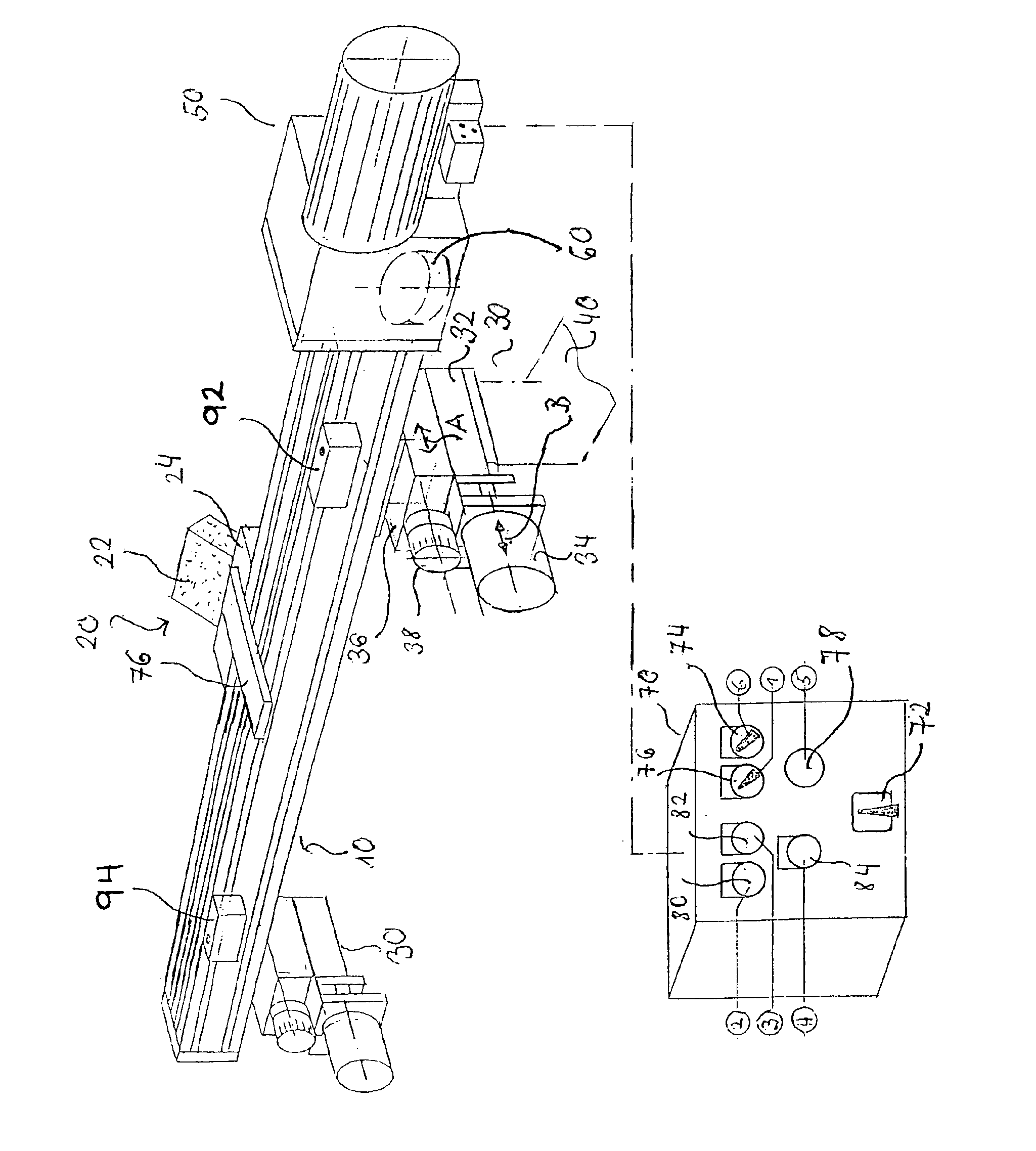
The device shown in the drawing comprises essentially a guide element realized as a straight guide rail 10, a dressing system 20 that can be moved along the guide rail 10, and an advancing mechanism that comprises a total of two advancing systems 30. The device shown in the drawing also comprises a drive mechanism 50, by which the dressing system 20 can be moved along the guide rail 10. To this end, the drive mechanism 50 is releasably coupled to the dressing system 20 by an electromagnetic coupling.

Each of the advancing systems 30 comprises a first advancing slide 32, which is mounted on a support element 40, which is only schematically indicated. The first advancing slide 32 can be moved in a direction perpendicular to the path predetermined by the guide rail 10. Each advancing system 30 also comprises a second slide 36, which can be moved perpendicularly to the path predetermined by the guide rail 10 in the direction relative to the first advancing slide 32 indicated by the doubl...


PUM

PropertyMeasurementUnit
lengthaaaaaaaaaa
elasticaaaaaaaaaa
wear resistanceaaaaaaaaaa

Abstract

A device for dressing a card clothing, especially an all-steel sawtooth clothing, drawn over a preferably cylindrical drum, with a dressing system that can be moved along a path predetermined by a guide element, so that at least one element of the dressing system can be advanced in a direction that runs transversely, especially perpendicularly, to the predetermined path. The device has a remote-controlled advancing mechanism for advancing the one or more elements of the dressing system.

Description

BACKGROUND OF THE INVENTIONThe invention relates to a device for dressing a card clothing, especially an all-steel sawtooth clothing, drawn over a cylindrical drum, with a dressing system that can be moved along a path predetermined by a guide element. At least one element of the dressing system can be advanced in a direction that runs transversely, especially perpendicularly, to the predetermined path.In the processing of textile fibers, the fibers are straightened and cleaned with the use of cards or carding machines. These carding machines comprise a cylindrical drum, whose outer cylindrical surface is covered with card clothing. The carding operation is carried out by rotating the cylindrical drum about its cylinder axis. The clothing mounted on the cylindrical surface runs through the fiber material and straightens it, possibly in interaction with other processing elements, such as card flats, helical rollers, and the like. In addition, this carding also cleans the raw material...

Claims


Application Information

Patent Timeline
Patent Type & Authority Patents(United States)
IPC IPC(8): B24B19/18B24B19/00D01G15/38D01G15/00D01G15/76D01G15/84
CPCD01G15/38B24B19/18
Inventor GRAF, RALPH A.
Owner GRAF CIE AG
Learn More