Exhaust gas purifying filter and manufacturing method therefor
a technology manufacturing method, which is applied in the direction of machines/engines, filament/thread forming, chemical/physical processes, etc., can solve the problems of difficult to smoothly deform the bulkhead b>81/b> into a desired profile, time-consuming soaking, and insufficient purification efficiency of exhaust gas purification. , to achieve the effect of high purification efficiency, easy manufacturing, and smooth introduction into and discharg
- Summary
- Abstract
- Description
- Claims
- Application Information
AI Technical Summary
Benefits of technology
Problems solved by technology
Method used
Image

Examples
embodiment 1
[0054]Referring to FIGS. 1 to 7, an exhaust gas purifying filter and method of manufacturing the exhaust gas purifying filter of an embodiment of the present invention will be explained below.
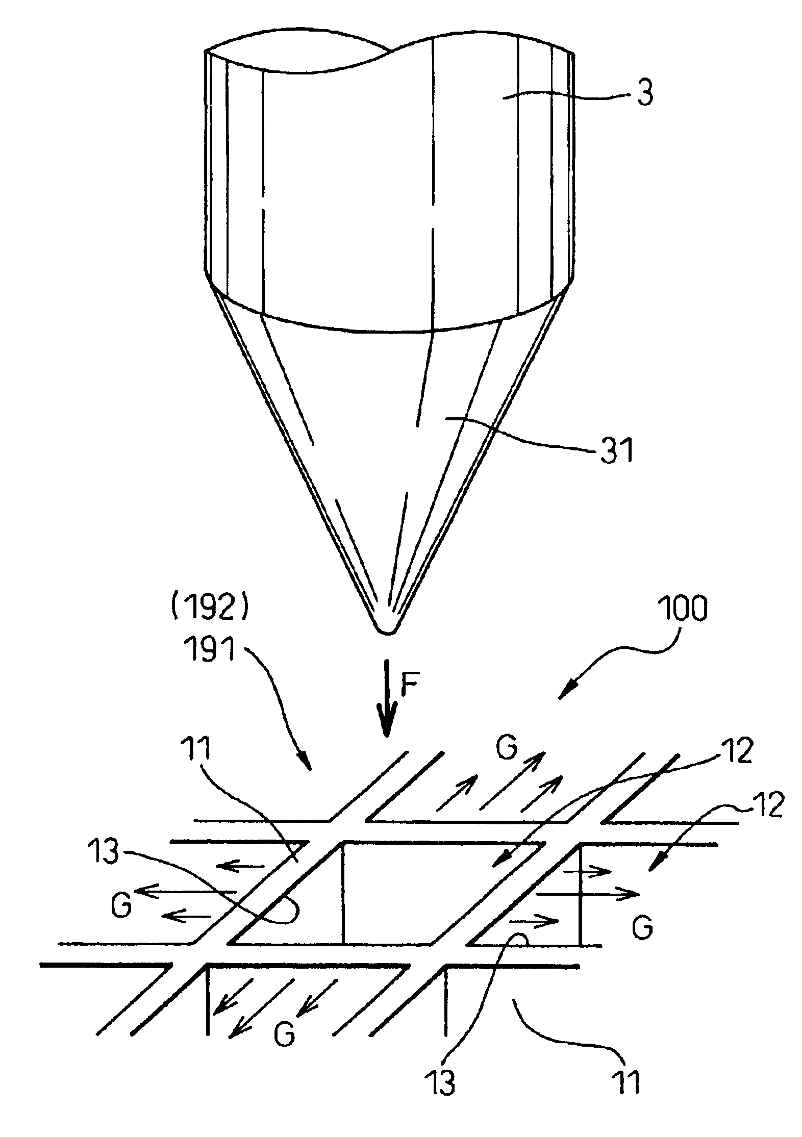
[0055]According to the method of manufacturing the exhaust gas purifying filter of this embodiment, as shown in FIG. 7, particulates contained in the exhaust gas 4, which is discharged from an internal combustion engine such as a Diesel engine, are collected so that the exhaust gas 4 can be purified by the exhaust gas purifying filter 1.
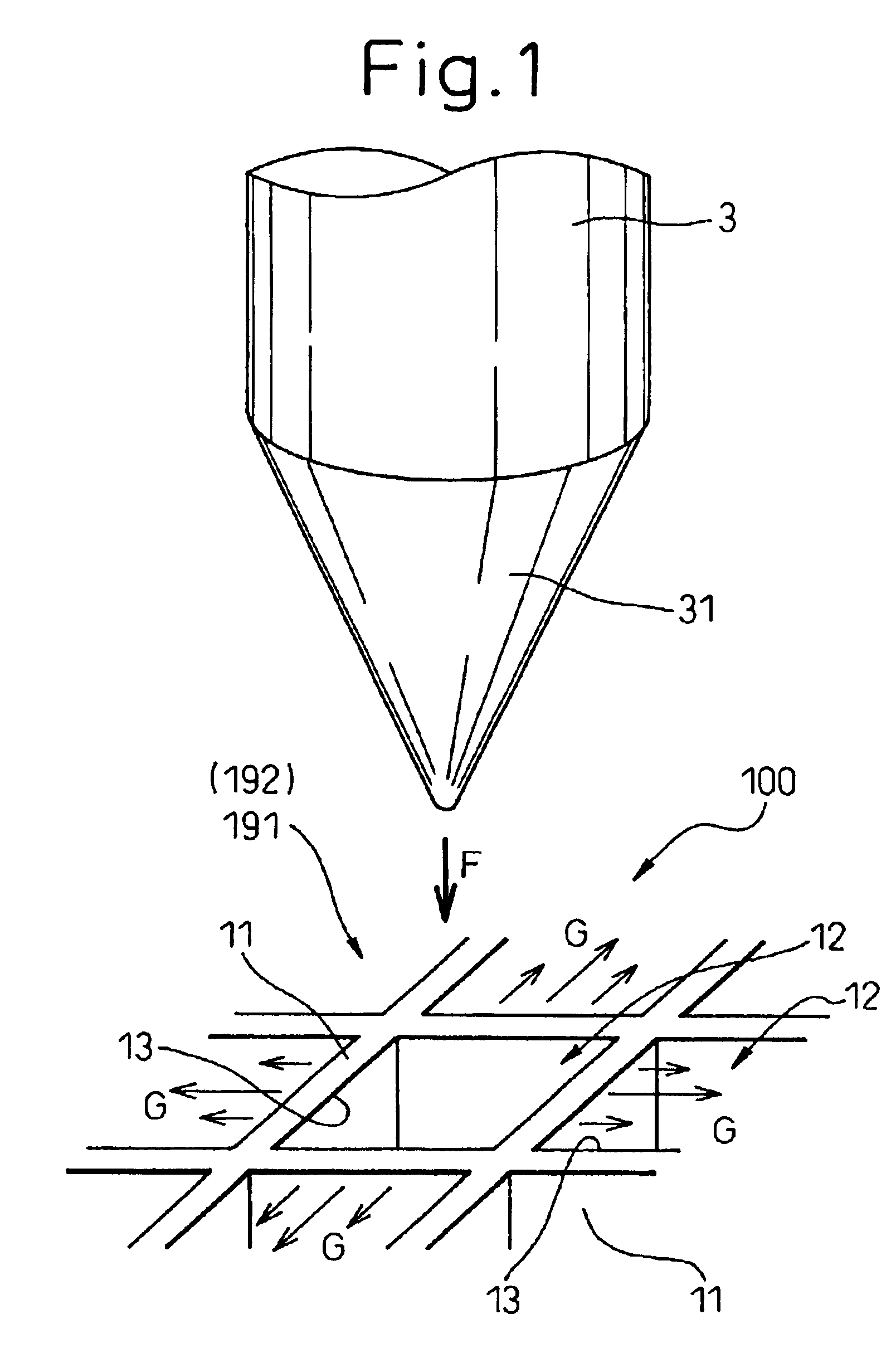
[0056]First, ceramic materials containing organic binder and thermo-plastic resin are formed into a honeycomb structure by extrusion and dried and cut into a predetermined length, so that the honeycomb body 100 shown in FIG. 2 is made. As shown in FIGS. 2, 3A and 4, the honeycomb body 100 includes honeycomb-shaped bulkheads 11 and a plurality of cells 12 which are partitioned by the bulkheads 11 and penetrate both end faces 191, 192.
[0057]Next, as shown by arrow...
embodiment 2
[0095]In this embodiment, the forward end portion 31 of the tapered jig 3 used for deforming the bulkheads 11 is substantially formed into a quadrangular pyramid as shown in FIGS. 8 and 9.
[0096]In this case, when the forward end portion 31 of the tapered jig 3 is inserted into the opening portion 13 of the cell 12 of the honeycomb body 100, the corners 32 of the forward end portion 31 are respectively made to come into contact with the substantial centers of the sides of the opening portion 13 as shown in FIG. 8.
[0097]In the thus obtained exhaust gas purifying filter 1, the large opening portion 131 is formed into a substantial square as shown in FIG. 9.
[0098]Other points of the construction are the same as those of Embodiment 1.
[0099]The operation and effect of this embodiment are the same as those of Embodiment 1.
embodiment 3
[0100]In this embodiment, the honeycomb body 100 is fired before the paste 140 is coated.
[0101]After the bulkheads 11 of the cell 12 of the honeycomb body 100 have been deformed, the honeycomb body 100 is fired. After that, the paste 140 is coated, and then the honeycomb body 100 is fired again.
[0102]Other points are the same as those of Embodiment 1.
[0103]In this case, the percent defective of defectives caused in the process of firing can be reduced.
[0104]The operation and effect of this embodiment are the same as those of Embodiment 1.
PUM
| Property | Measurement | Unit |
|---|---|---|
| Area | aaaaa | aaaaa |
Abstract
Description
Claims
Application Information
 - R&D
- Intellectual Property
- Life Sciences
- Materials
- Tech Scout
- Unparalleled Data Quality
- Higher Quality Content
- 60% Fewer Hallucinations
Browse by: Latest US Patents, China's latest patents, Technical Efficacy Thesaurus, Application Domain, Technology Topic, Popular Technical Reports.
© 2025 PatSnap. All rights reserved.Legal|Privacy policy|Modern Slavery Act Transparency Statement|Sitemap|About US| Contact US: help@patsnap.com