

Fiber-reinforced matrix compositions
a fiber reinforced and matrix technology, applied in the direction of synthetic resin layered products, filament/thread forming, water-setting substance layered products, etc., can solve the problems of troublesome, insufficient fiber dosage, and significant variation in the material properties of fiber reinforced materials, so as to achieve the effect of ease of dispersibility
- Summary
- Abstract
- Description
- Claims
- Application Information
AI Technical Summary
Benefits of technology
Problems solved by technology
Method used
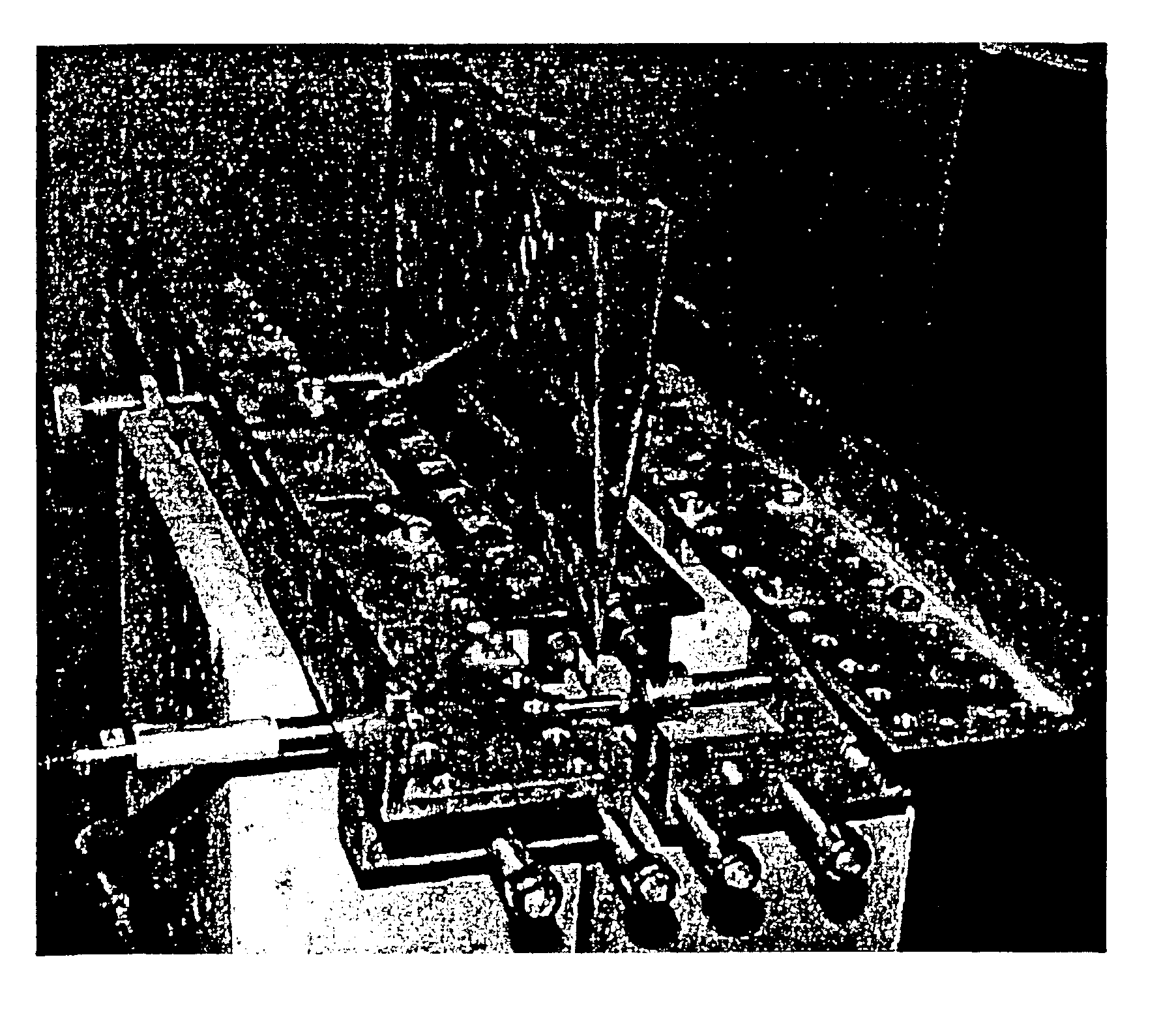
Image

Examples
example 1
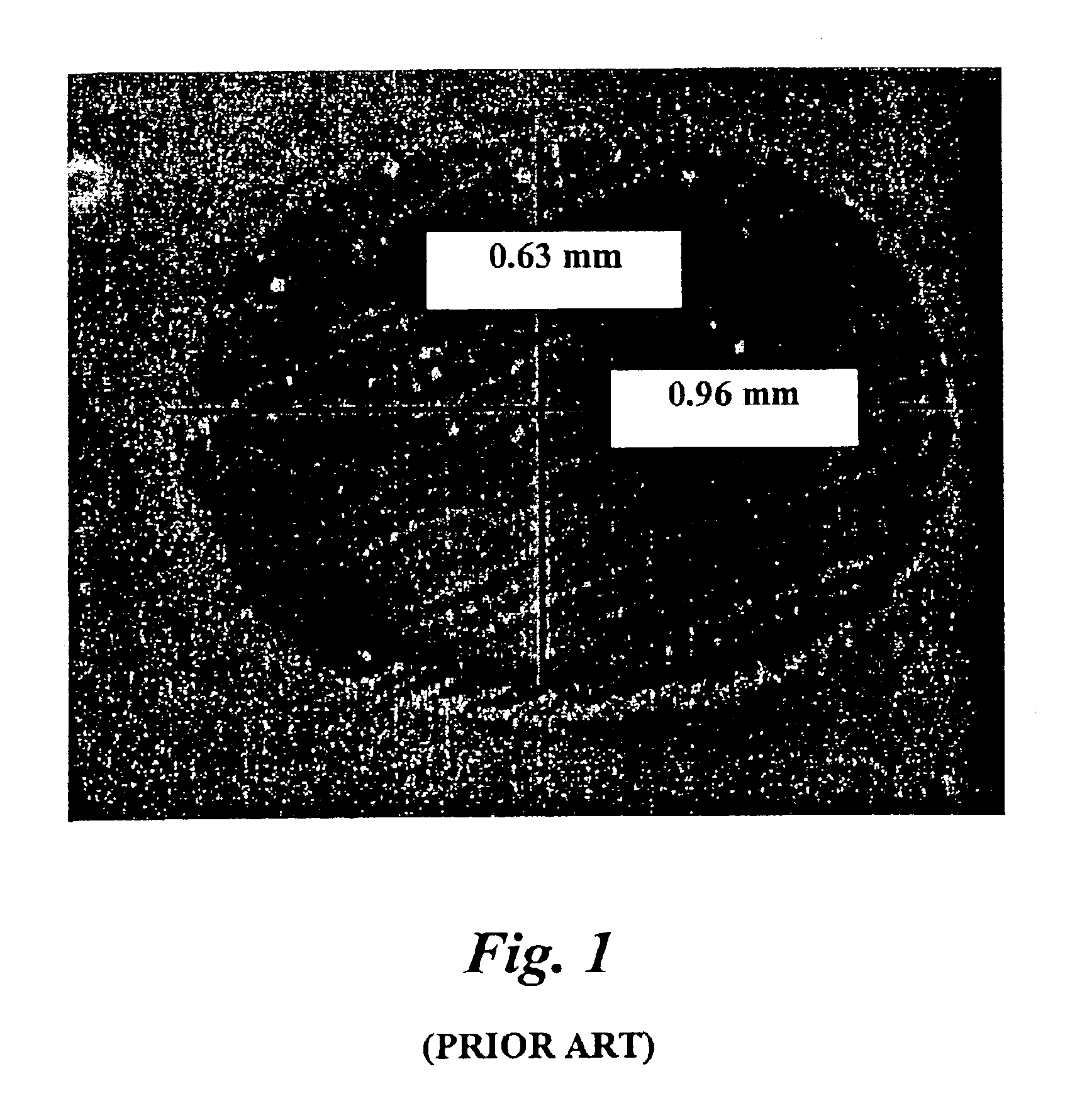
Prior Art
Prior art fibers having an elliptical shaped cross section were tested in terms of bendability and dispersibility in a concrete mix. These elliptical fibers were 50 mm long, 1.14 mm wide, 0.44 mm. thick, and had a Young's modulus of elasticity of 4 Giga Pascal. The “bendability” formula discussed above may be employed, wherein bendability “B” was computed as B=1 / (3·E·I), and the moment of inertia “I” for ellipses is calculated by the formula, Iellipse=Pi / 64·a·b3, where “a” is half the width of the elliptical fiber (major axis of the ellipse, i.e., widest dimension through the center) and “b” is half the thickness of the elliptical fiber (minor axis of the ellipse, i.e. thinnest dimension through the center point of the ellipse). The bending deflection “B” was computed to be 17.5 mN−1*m−2. This fiber is considered a “stiff” fiber. 30 minutes were required for introducing 100 pounds of these elliptical fibers into 8 cubic yards of concrete. The concrete resided in the drum of...
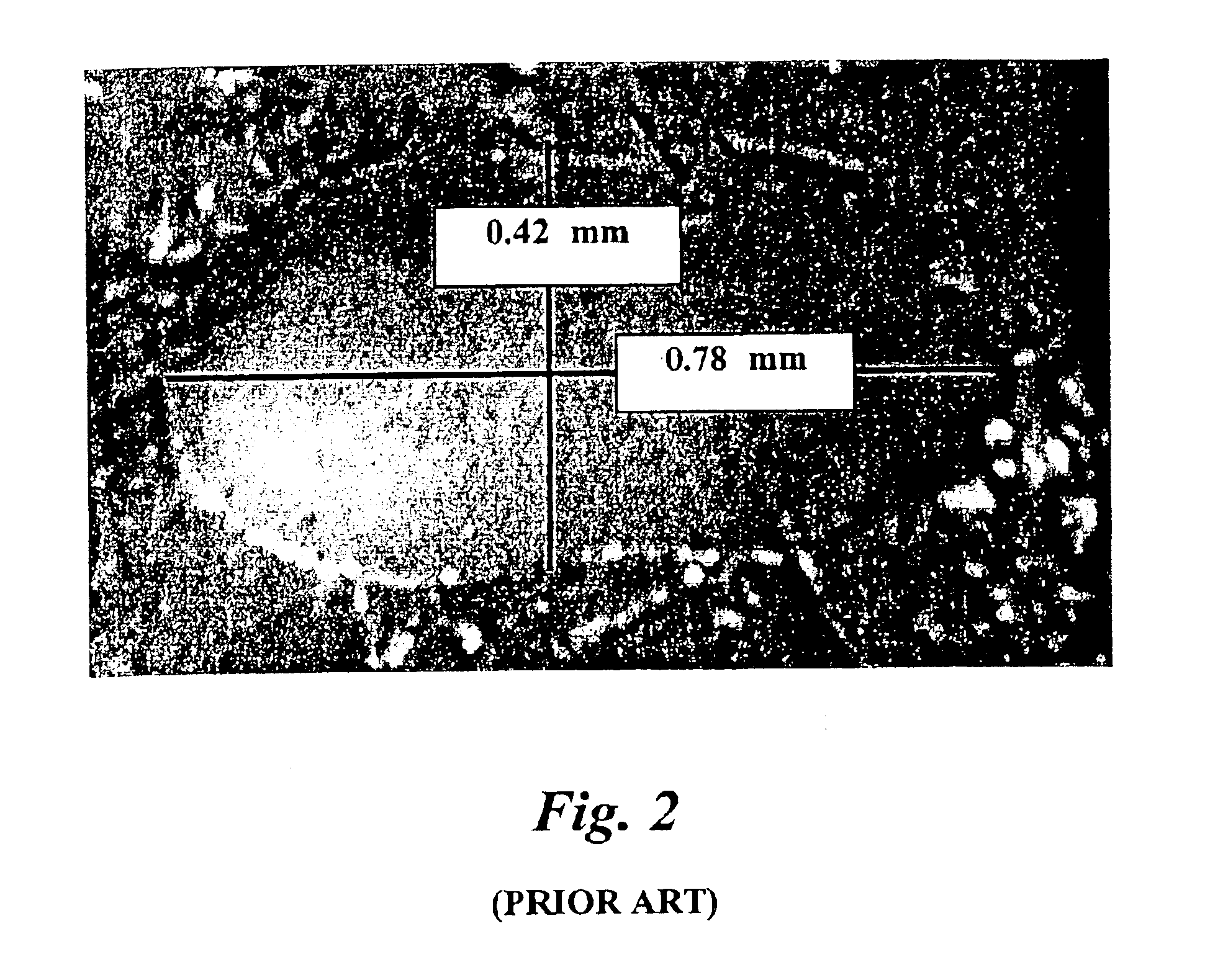
example 2
In contrast to the prior art elliptical fibers of Example 1, fibers having a generally quadrilateral cross-section were used. These quadrilateral fibers had the following average dimensions: 50 mm long, 1.35 mm wide, and 0.2 mm thickness, with a Young's modulus of elasticity of 9 Giga Pascal. The bendability “B” of these fibers was computed in accordance with the formula, B=1 / (3·E·I), wherein the moment of inertia “I” for rectangular cross-section was computed in accordance with the formula, Irectangle={fraction (1 / 12)}·w·t3, wherein “w” is the average width and “t” is the average thickness of the rectangle. Using the equation, the bendability “B” was computed as 41.2 mN−1*m−2. This fiber is considered flexible. When 100 pounds of these fibers were introduced into 8 cubic yards of concrete, located in a ready-mix truck drum and rotated at the same rate as in Example 1, a homogeneous fiber distribution was achieved in just 5 minutes. No fiber balling was observed.
example 3
The mechanical properties of the fibers themselves have a huge impact on the behavior of the fibers in concrete, if there is sufficient bond between the fiber and the brittle concrete matrix. If the fibers have not bonded well to the matrix (e.g. fiber pull-out is the major fiber failure mechanism observed when the fiber reinforced concrete is broken apart), then the fiber properties will have minimal impact on the behavior of the composite material. As mentioned earlier, due to the fiber geometry and dimensional ranges inventively selected by the present inventors, sufficient bond adhesion between the matrix material (when hardened) and the fibers can be achieved to obtain, ideally, half fiber failure (breakage) and half fiber pull-out. Therefore, fiber properties such as elastic modulus of elasticity, tensile strength, and minimum load carrying capacity were selected so as to maintain as closely as possible the ideal 50:50 balance between fiber pull-out failure and fiber failure. ...
PUM
| Property | Measurement | Unit |
|---|---|---|
| width | aaaaa | aaaaa |
| width | aaaaa | aaaaa |
| thickness | aaaaa | aaaaa |
Abstract
Description
Claims
Application Information