Winch controller

Active Publication Date: 2005-03-08
WARN INDUSTRIES +1
View PDF5 Cites 57 Cited by
  • Summary
  • Abstract
  • Description
  • Claims
  • Application Information

AI Technical Summary

Benefits of technology

The winch controller of the present invention provides an electronic replacement of the electromechanical solenoid switches used on conventional winches. The heart of the controller utilizes four high current electronic switches that change the direction of the field current for changing the direction of rotation of the winch motor. The high current electronic switches are operated using low curren

Problems solved by technology

Winches typically have an upper load limit.
Potential damage or actual damage may occur when a winch is driven beyond its load limit; i.e., placed under a load condition exceeding its load limit.
In addition, continued use of a winch under heavy load can cause the motor and other components of the winch to heat up.
As the temperature of the motor or other components reach a predetermined maxi

Method used


Image

  • Winch controller
  • Winch controller
  • Winch controller

Examples


Embodiment Construction

The following description of the preferred embodiment(s) is merely exemplary in nature and is in no way intended to limit the invention, its application, or uses.

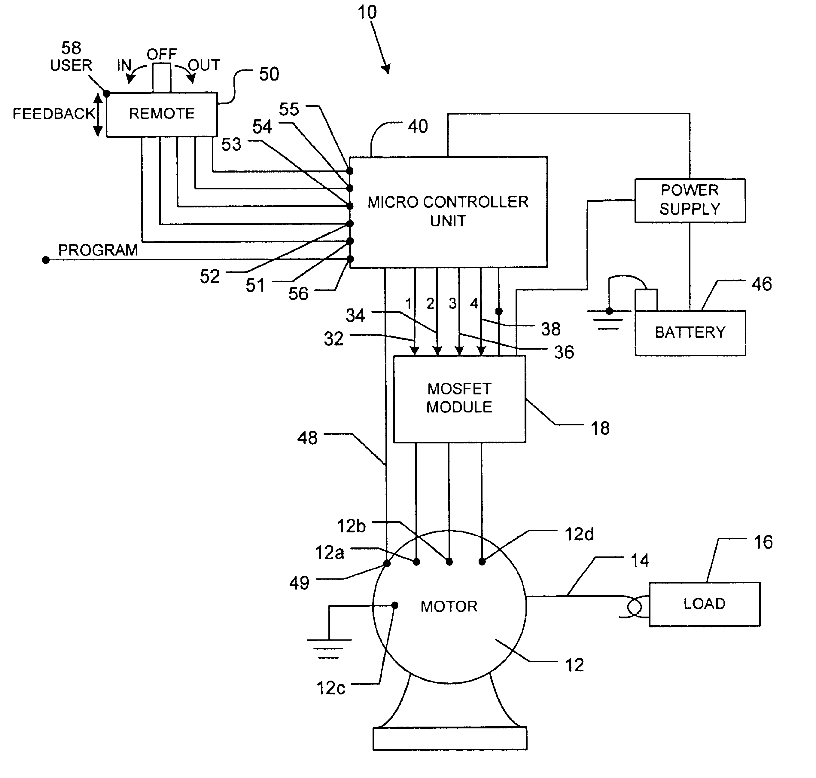
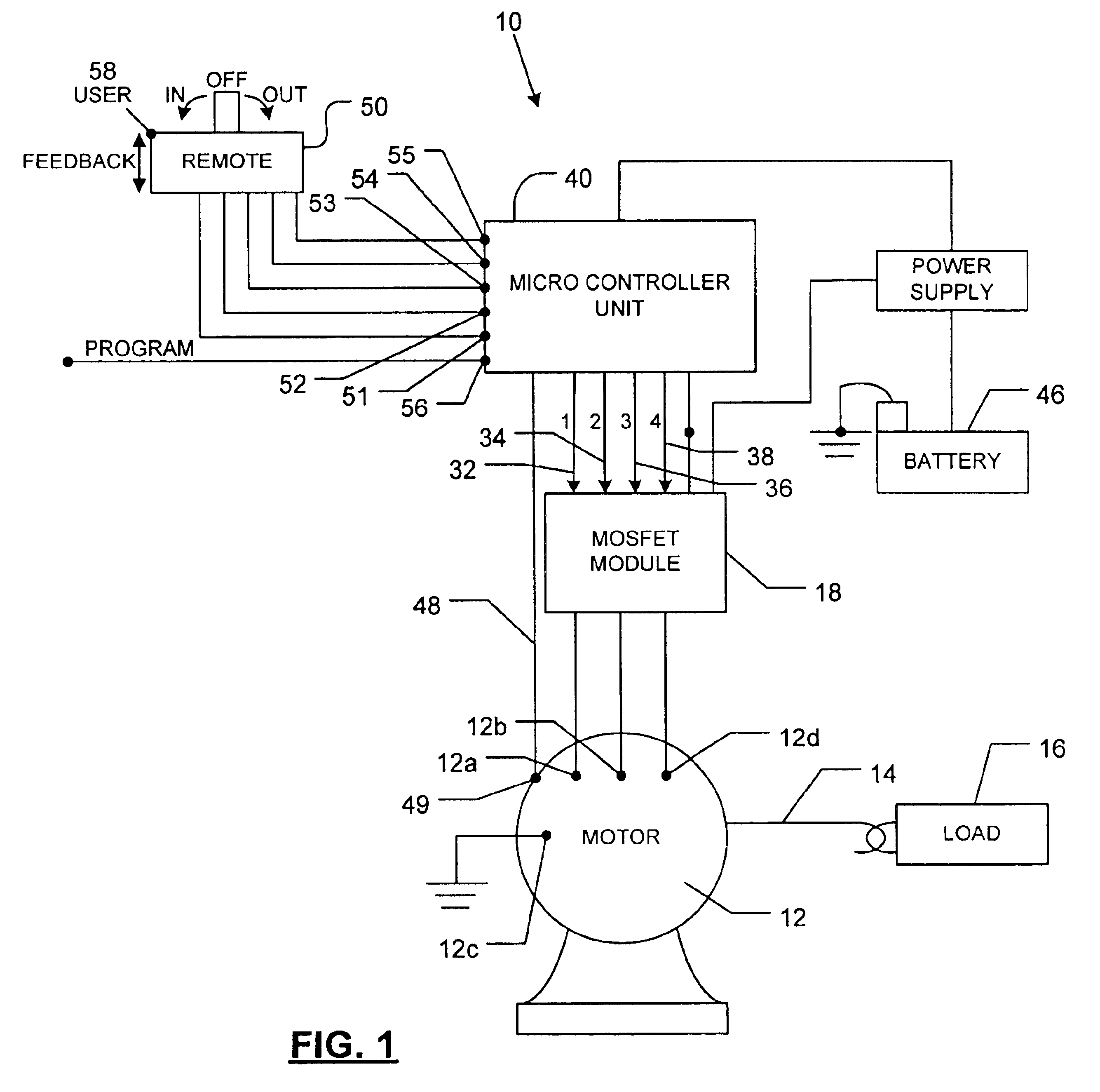
FIG. 1. illustrates a winch system 10 in accordance with a preferred embodiment of the present invention. Winch system 10 includes an electric motor 12 with a spool (not shown) for deploying or collecting a cable 14 attached to a load 16. Control terminals 12a and 12b of motor 12 provide electric current to the field coil of the motor 12 for causing motor 12 to operate in one of two rotational directions. A third terminal 12c of motor 12 ties to ground potential and a fourth terminal 12d is connected to the armature of the motor 12.

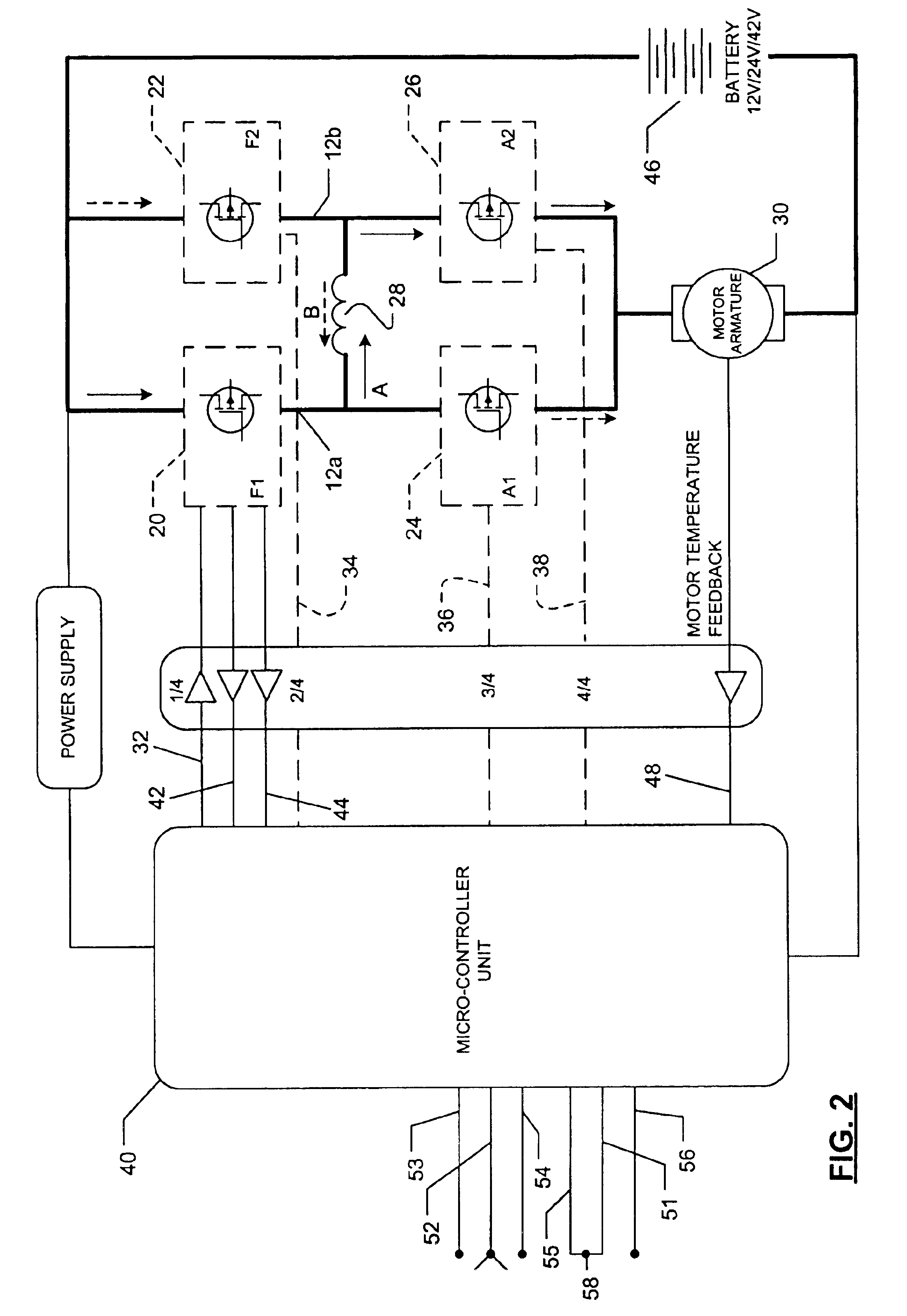
A MOSFET module 18 is provided for controlling the direction of current through the field coil of the motor 12. In particular, the MOSFET module 18 includes four high current electronic switches 20, 22, 24, 26 (best shown in FIG. 2) based on silicon MOSFET technology. The. MOSFET technology minim...


PUM


Abstract

A solid state controller is provided for a winch and includes fault detection for several parameters and overload interrupt controlled by the controller. The system uses a single controller that can be programmed for several different products and utilizes MOSFET switches for alternating the direction of current

Description

FIELD OF THE INVENTIONThe present invention relates to a winch, and more particularly to a solid state controller for a winch.BACKGROUND AND SUMMARY OF THE INVENTIONWinches support a wide range of applications and assume a variety of sizes and types. Winches typically have an upper load limit. Potential damage or actual damage may occur when a winch is driven beyond its load limit; i.e., placed under a load condition exceeding its load limit. In addition, continued use of a winch under heavy load can cause the motor and other components of the winch to heat up. As the temperature of the motor or other components reach a predetermined maximum, the motor and / or circuit components become susceptible to damage, as well.Accordingly, it is desirable to provide a system that is capable of detecting an overload condition of the winch and interrupting operation of the motor in order to prevent damage due to overload. It is also desirable to provide a fault detection system that monitors oper...

Claims


Application Information

Patent Timeline
IPC IPC(8): H02P1/00H02P1/18H02P1/22B60P3/12B66D1/12B66D1/46B66D1/58
CPCB60P3/12B66D1/12B66D1/58B66D1/46Y10S388/933
Inventor HERAVI, OLIVERBRUNE, CHRISTOPHER S.LAWSON, MITCHELL R.
Owner WARN INDUSTRIES
Why Eureka
Try Eureka