
Insertion device for gradient coils of a magnetic resonance apparatus

a magnetic resonance apparatus and gradient coil technology, applied in the direction of magnetic variable regulation, process and machine control, instruments, etc., can solve the problems of high time and extension expenditure of operating personnel, and require several hours, and achieve simple and reliable insertion and easy handling

Inactive Publication Date: 2005-03-08
SIEMENS HEALTHCARE GMBH
View PDF21 Cites 14 Cited by
  • Summary
  • Abstract
  • Description
  • Claims
  • Application Information

AI Technical Summary

Benefits of technology

An object of the invention is to provide a mechanism that enables a simple and reliable insertion of a local gradient coil unit in different magnetic resonance apparatuses and thus can be easily handled.
This object is achieved according to the invention in a device for inserting a gradient coil unit into the examination space of a magnetic resonance apparatus thus has a movable carrier unit with a boom (cantilevered arm) that can be extended in the horizontal direction, is connected to the movable carrier unit, the boom accepting the gradient coil unit and entering with the gradient coil unit into the examination space of the magnetic resonance apparatus. The inventive device is autonomous, i.e. it operates independently of the patient bed of the magnetic resonance apparatus and can be employed in existing magnetic resonance apparatus. An easily released connection between the extensible boom and the gradient coil unit enables the employment of different gradient coil units for different applications. A variable height positioning of the extensible boom enhances the adaptability to different magnetic resonance apparatuses and—in combination with the movable carrier unit—facilitates removal and storing of the gradient coil unit. The boom that is extensible in horizontal direction can be designed such that it makes available the electrical connections necessary for supplying the gradient coil unit with power. This shortens the fitting times and enhances the security during operation. Additional stability and guidance when introducing the gradient coil unit are achieved in an embodiment having a glide mechanism at the horizontally extensible boom in combination with a corresponding design in the examination space of the magnetic resonance apparatus. A locking arrangement attached to the boom and / or to the gradient coil unit in combination with a corresponding design in the examination space of the magnetic resonance apparatus enables a reliable positioning of the gradient coil unit in the examination space. Little space is required when inserting and removing the introduction mechanism in an embodiment wherein the boom can be extended in telescoping fashion. A docking device attached to the introduction mechanism for docking at the magnetic resonance apparatus provides additional stability during operation and facilitates the insertion of the gradient coil unit into the examination space of the magnetic resonance apparatus.

Problems solved by technology

In some embodiments of local gradient coils the securing of the local radio-frequency antenna in the magnetic resonance apparatus and the removal therefrom can require several hours, since the whole-body antenna of the magnetic resonance apparatus must be un-installed and re-installed in some cases.
Heretofore, the insertion and mounting of the local gradient coils, which can have a weight of up to 250 kg, has only been manually possible and requires a high outlay of the operating personnel in terms of time and extension.

Method used


Image

  • Insertion device for gradient coils of a magnetic resonance apparatus
  • Insertion device for gradient coils of a magnetic resonance apparatus
  • Insertion device for gradient coils of a magnetic resonance apparatus

Examples


Embodiment Construction

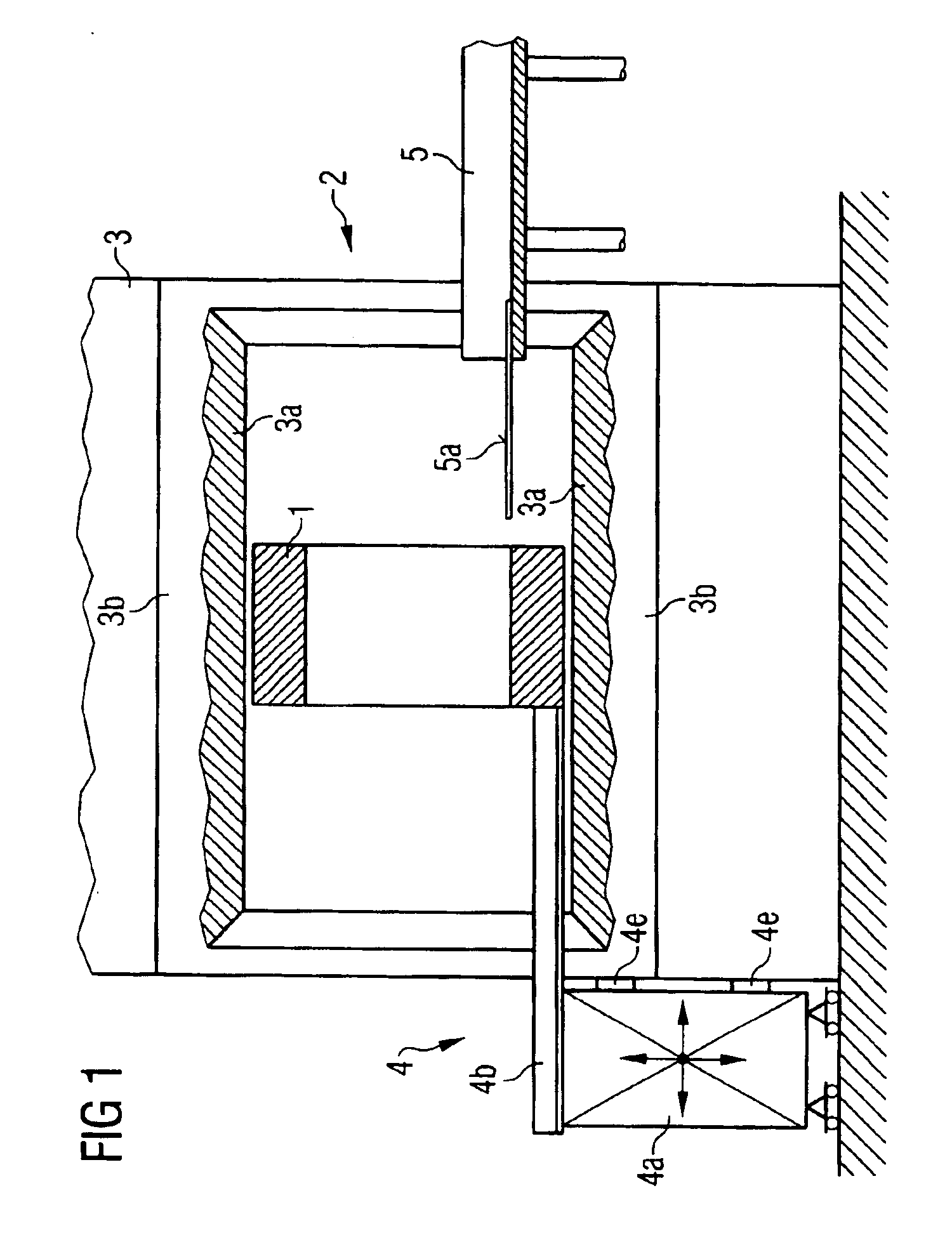
As an example, FIG. 1 shows an arrangement for examining the head of a patient by means of a local gradient coil unit 1. To this end, the head of the patient on a head support 5a is positioned in the local gradient coil unit 1.

For generating a static basic magnetic field, the magnetic resonance apparatus 3 has an essentially hollow-cylindrical superconducting basic field magnet 3b. A gradient coil system 3a for generating gradient fields, which is likewise essentially hollow-cylindrical, is permanently installed in a hollow opening or tunnel of the basic field magnet 3b.

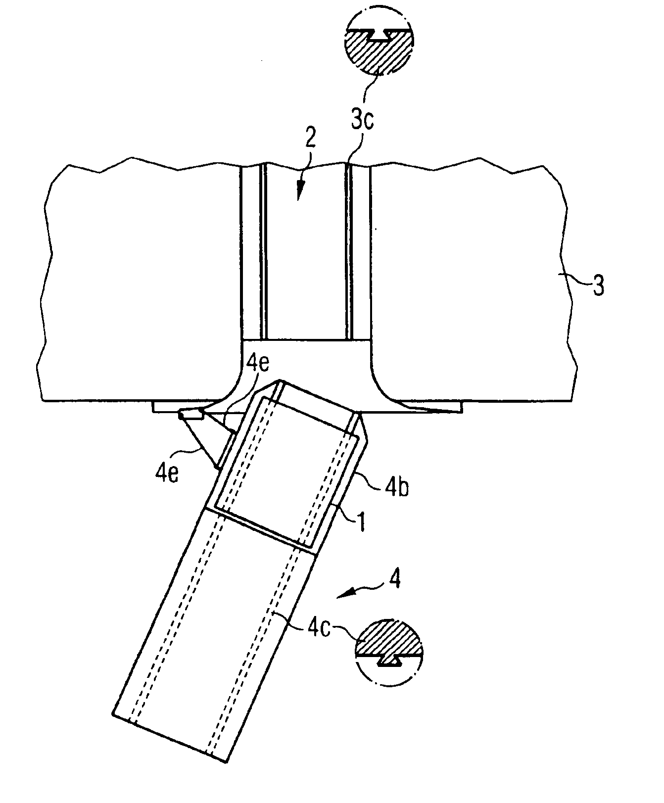
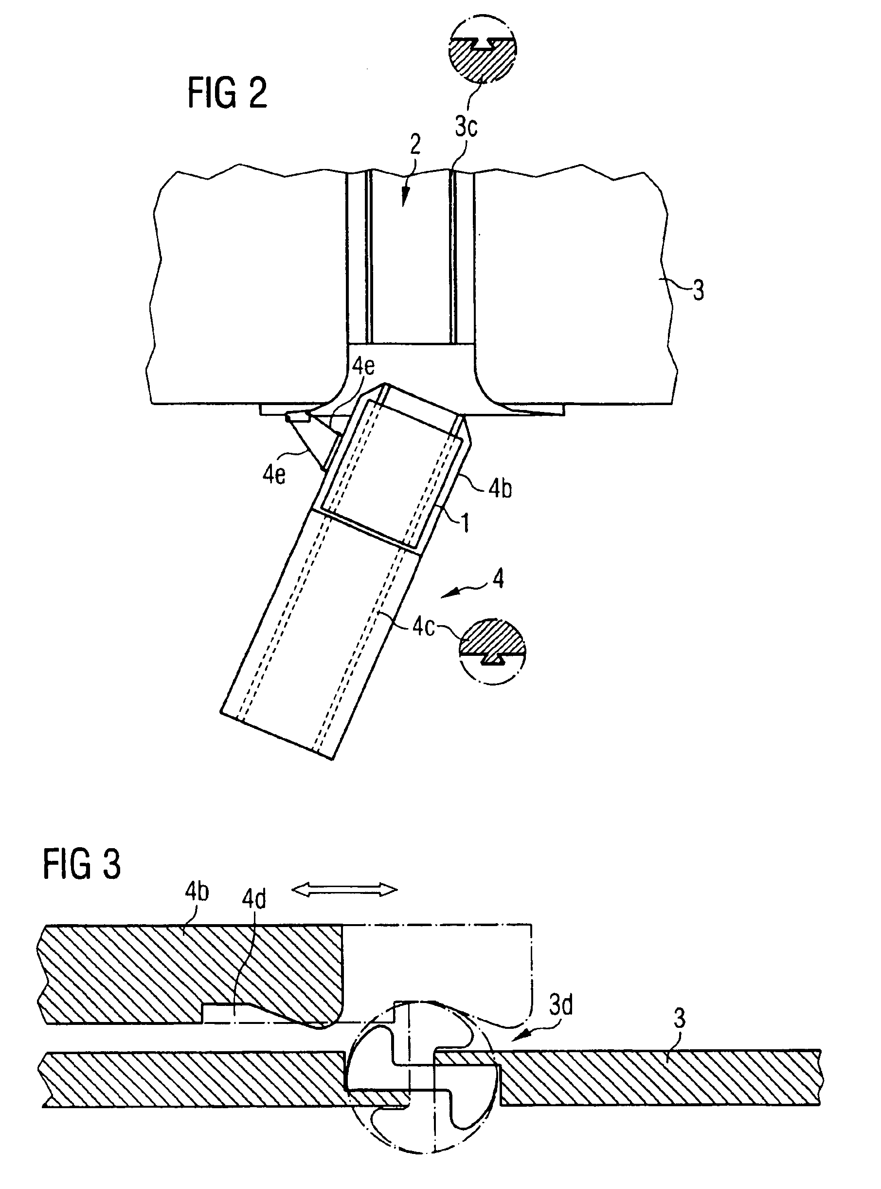
The inventive insertion device 4 is composed of a separate carrier unit 4a, movable, for example, with rollers, and an extensible boom 4b that is attached to the movable carrier unit 4a and carries the gradient coil unit 1. In the state shown in FIG. 1, the gradient coil unit 1 already has been inserted and positioned. During operation, the gradient coil unit 1 is held in the examination space 2 by the boom 4b. A do...


PUM


Abstract

A device for inserting local gradient coils (insert gradient coils) into a magnetic resonance apparatus has movable carrier unit and a boom that is extensible in the horizontal direction, the boom being connected to the movable carrier unit and accepting the gradient coil unit and inserting it into the examination space of the magnetic resonance apparatus.

Description

BACKGROUND OF THE INVENTION1. Field of the InventionThe present invention is directed to a device for the insertion of local gradient colls into a magnetic resonance apparatus.2. Description of the Prior ArtMagnetic resonance systems have been employed for many years in medicine and in biophysics for acquiring images from the inside of the body of an examination subject. Magnetic resonance tomography is based on the physical phenomenon of nuclear magnetic resonance. In the examination procedure, the examination subject is exposed to a strong, constant magnetic field, causing the previously irregularly oriented nuclear spins of the atoms to align in the examination subject. These unordered nuclear spins are excited to a specific oscillations (resonant frequency) by means of radio-frequency waves. This oscillation generates the actual measured signal (RF response signal) for the actual image acquisition in magnetic resonance tomography that is picked up by suitable reception coils.A p...

Claims


Application Information

Patent Timeline
IPC IPC(8): G01R33/385G01R33/38G01R33/28
CPCG01R33/385
Inventor SCHUSTER, JOHANNSTOCKER, STEFAN
Owner SIEMENS HEALTHCARE GMBH
Learn More