
Supporting structure for concurrently supporting a plurality of containers for substances for pharmaceutical, medical or cosmetic applications, transport structure and transport or packaging container comprising the same

a support structure and container technology, applied in the direction of pharmaceutical containers, packaging foodstuffs, packaged goods types, etc., can solve the problems of complex post-processing in the tool, high cost, and many additional requirements of the supporting structure, and achieve the effect of convenient and cost-effective manufacturing, precise positioning of the containers, and high packing density

Active Publication Date: 2022-03-29
SCHOTT PHARMA SCHWEIZ AG
View PDF44 Cites 0 Cited by
  • Summary
  • Abstract
  • Description
  • Claims
  • Application Information

AI Technical Summary

Benefits of technology

[0015]It is an object of the present disclosure to provide an enhanced supporting structure for concurrently supporting a plurality of containers for substances for pharmaceutical, medical or cosmetic applications that can be easily and cost-effectively manufactured, avoids a glass-to-glass contact between the containers held on the supporting structure in a simple manner, allows for high packing density and enables a precise positioning of the containers, wherein preferably a simple and reliable insertion of the containers into the receptacles of the supporting structure shall be possible. Further aspects of the present disclosure relate to transport structures or transport or packaging containers and to a sterile packaging structure comprising such a supporting structure.

Problems solved by technology

This results in numerous additional requirements on the supporting structure, especially with regard to the accuracy of the positions of the containers in the supporting structure.
The insertion of the containers from above into the receptacles of the supporting structures always requires a very precise pre-positioning of the containers relative to the receptacles, which is a complex task.
A subsequent post-processing in the tool is very complicated, so that certain deviations in the geometry cannot be avoided.
In particular, the demolding bevels lead to an increased tilting of the containers in the receptacles, which leads to difficulties for the automated filling process and in particular for stoppering, particularly with relatively long and slim containers, for example when stoppering cartridges.
Such large demolding bevels, however, cause a relatively inaccurate guidance and cause a lower packing density, particularly in the case of relatively long and slim containers such as cartridges.
Relatively large minimum distances must therefore be maintained between the individual receptacles of the supporting structure, which limits the packing density that can be accomplished.
However, such measures for reinforcement of the supporting structure usually result in a higher weight and in higher material costs for the supporting structure.

Method used


Image

  • Supporting structure for concurrently supporting a plurality of containers for substances for pharmaceutical, medical or cosmetic applications, transport structure and transport or packaging container comprising the same
  • Supporting structure for concurrently supporting a plurality of containers for substances for pharmaceutical, medical or cosmetic applications, transport structure and transport or packaging container comprising the same
  • Supporting structure for concurrently supporting a plurality of containers for substances for pharmaceutical, medical or cosmetic applications, transport structure and transport or packaging container comprising the same

Examples


first embodiment

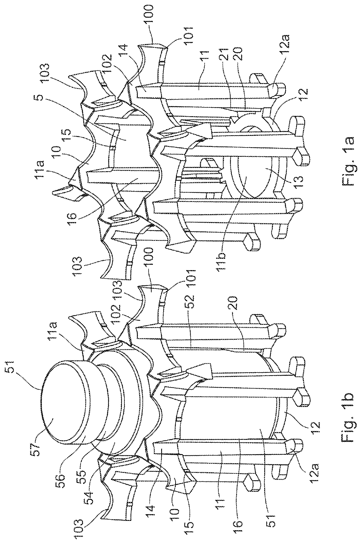
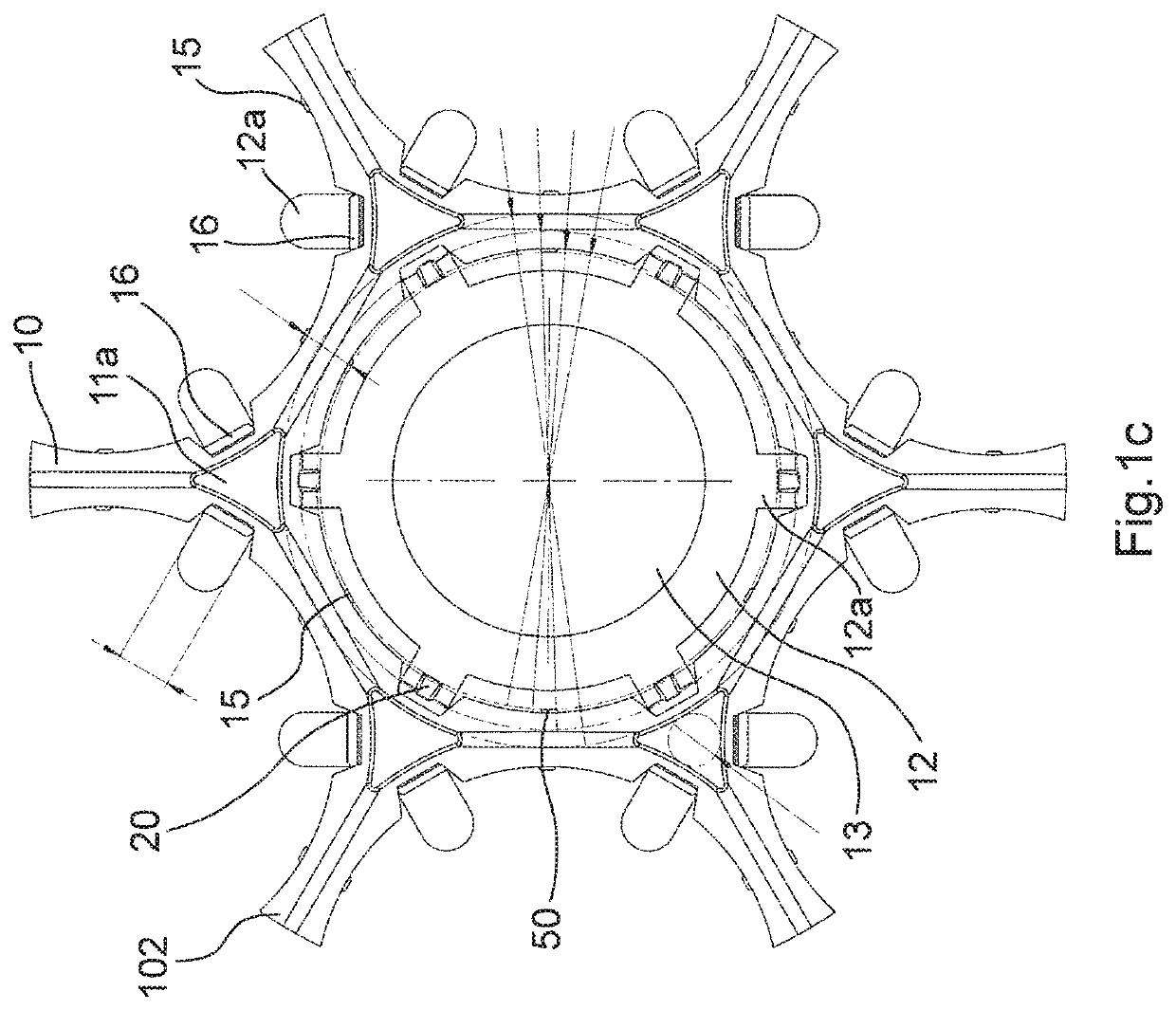
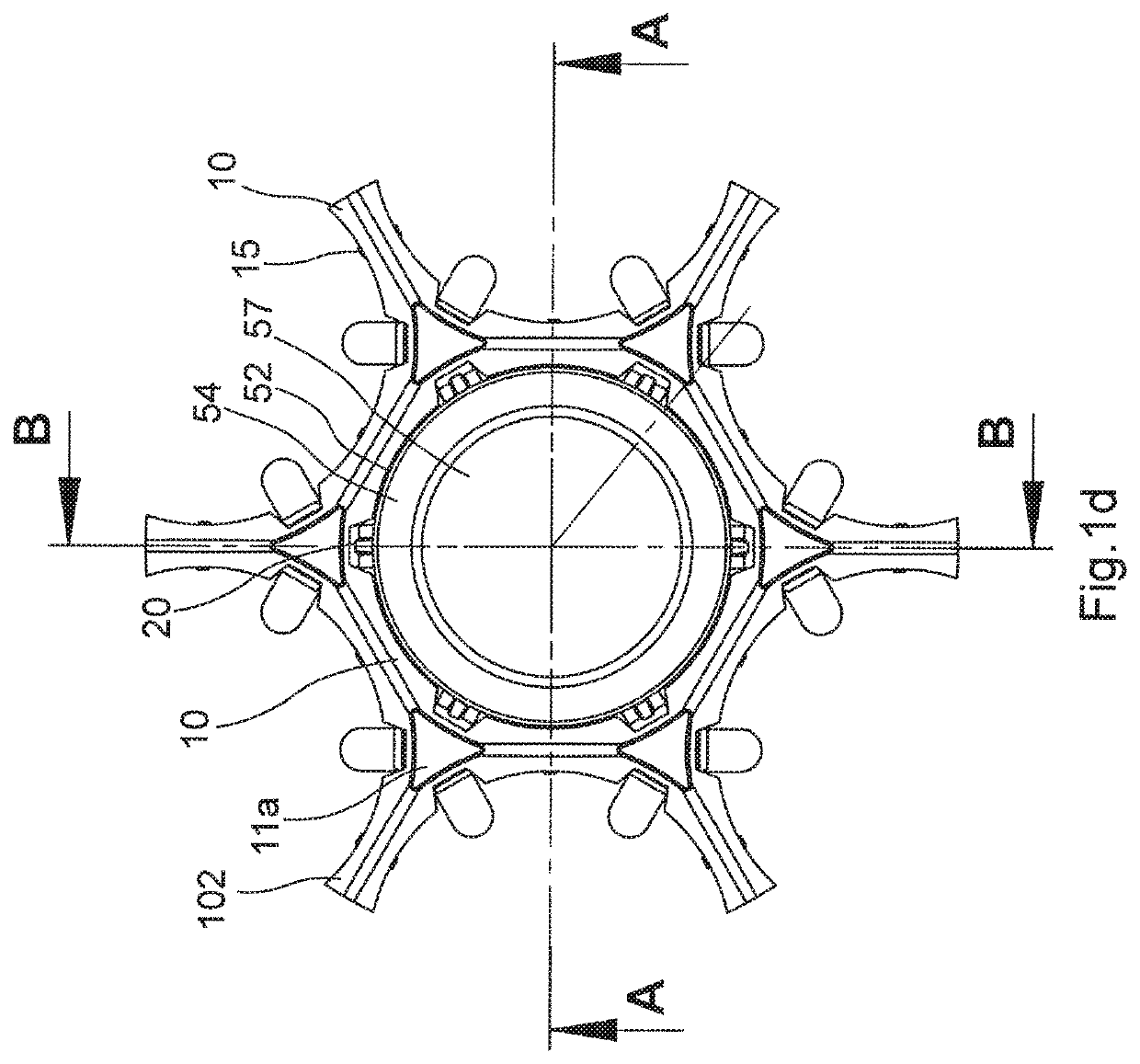
[0105]FIG. 1g shows the general configuration of a supporting structure 1 according to the present disclosure. The supporting structure 1 has an upper side or base plane 2, which generally is formed as a plate and whose circumferential edge is formed flat as shown in FIG. 1g. In the upper side 2, a plurality of openings 5 is formed, which are arranged in rows and columns extending perpendicular to each other, wherein in this exemplary embodiment, the openings 5 of adjacent rows or columns are arranged staggered relative to each other, which enables a higher packing density with the hexagonal arrangement of the peripheral webs 10. A plurality of axial connecting webs 11 protrude perpendicularly from the underside of the supporting structure 1, which are connected to each other at their lower ends via circumferential bottom webs 12. As described in more detail below, receptacles are formed by the axial connecting webs 11 into which the containers can be inserted perpendicularly from a...

second embodiment

[0127]FIGS. 2a-2c show the general structure of a base unit of a supporting structure according to the present disclosure, in which the axial connecting webs 11 have a hexagonal profile and are formed in one piece with the peripheral webs 10.

[0128]FIG. 2d shows a supporting structure according to the second embodiment with such base units. As a difference to the first embodiment, supporting structures of identical configuration may be concatenated with each other, as disclosed in more detail in WO2014 / 009037 A1 of the Applicant, the content of which is hereby expressly incorporated by reference. According to FIG. 2d, a plurality of protrusions 30 and recesses 35 are formed alternately along the two longitudinal sides of the supporting structure 1 and at regular intervals from each other, each of which having a triangular or polyhedral base area, if viewed in a plan view, and being formed corresponding to each other. A latching of two supporting structures 1 can be achieved by a form...

third embodiment

[0129]FIGS. 3a-3c show the general configuration of a base unit of a supporting structure according to the present disclosure, in which the upper ends 11a of the axial connecting webs 11 are formed in rhombic form. Such a configuration is particularly suitable for a supporting structure in which the receptacles are arranged in rows and columns extending perpendicularly thereto in alignment without lateral offset.

[0130]The receptacles 5 are limited by only four axial connecting webs 11, wherein retaining protrusions 12b protrude perpendicularly therefrom at their lower ends. As a difference to the previous embodiments, these retaining protrusions 12b are not connected to each other via a bottom web, although such a bottom web may in principle also be provided here. However, an adequate stiffness may still be achieved by appropriate material thickness of the lower ends of the axial connecting webs 11 and of the retaining protrusions 12b. Such a supporting structure 1 is suitable e.g. ...


PUM

PropertyMeasurementUnit
angle of inclinationaaaaaaaaaa

Abstract

The present disclosure relates to a supporting structure for concurrently supporting a plurality of containers for substances for pharmaceutical, medical or cosmetic applications, having a plurality of receptacles for accommodating the containers therein at least partially. Each of the receptacles has an open upper end for inserting the containers into the receptacles and a lower end having a retaining portion for delimiting an axial movement of the containers in the receptacles. Guiding portions are provided for guiding the containers into the receptacles during insertion. The guiding portions can have upper guiding and positioning portions close to the upper ends of the receptacles and lower guiding and positioning portions close to the lower ends of the receptacles, which are formed separately from each other and delimit a radial movement of the containers in the receptacles.

Description

CROSS-REFERENCE TO RELATED APPLICATION[0001]The present application claims the benefit and priority of German Patent Application No. 10 2017 101 398.9, entitled “Supporting structure for concurrently supporting a plurality of containers for substances for pharmaceutical, medical or cosmetic applications, transport structure and transport or packaging container comprising the same”, filed on Jan. 25, 2017, the whole content of which is hereby incorporated by reference.BACKGROUND OF THE DISCLOSURE1. Field of the Disclosure[0002]The present disclosure relates to a supporting structure for concurrently supporting a plurality of containers for substances for pharmaceutical, medical or cosmetic applications and to a transport structure or a transport or packaging container comprising such a supporting structure and containers supported by it.2. Discussion of the Related Art[0003]As containers for the storage of medical, pharmaceutical or cosmetic preparations with liquid administration, p...

Claims


Application Information

Patent Timeline
Patent Type & Authority Patents(United States)
IPC IPC(8): B65D71/70A61J1/16A61J7/00B01L9/06B65B3/00B65D1/36B65D25/10B65B7/28B65B21/18B65B43/56
CPCB65D71/70A61J1/16A61J7/0069B01L9/06B65B3/003B65D1/36B65D25/108B01L2200/025B65B7/2814B65B21/18B65B43/56B65D1/42B65D81/05B65D85/42
Inventor KLOKE, ARNEKOMANN, CHRISTIAN
Owner SCHOTT PHARMA SCHWEIZ AG
Learn More