
Method of cooling system for a personal computer and personal computer

a cooling system and personal computer technology, applied in the direction of lighting and heating apparatus, electrical apparatus casings/cabinets/drawers, instruments, etc., can solve the problems of thermal deformation of the mechanism, the operation of other circuits of the personal computer may sometimes become unstable, and the air in the personal computer is exhausted

Inactive Publication Date: 2005-03-08
MAXELL HLDG LTD
View PDF33 Cites 22 Cited by
  • Summary
  • Abstract
  • Description
  • Claims
  • Application Information

AI Technical Summary

Benefits of technology

The personal computer of the invention comprises: a heat transfer part, which receives the heat generated from a heat-generating part within the personal computer and releases the heat to the outside of the personal computer; a main body of the personal computer, which is provided with a connector for establishing an electric connection; and a cooling unit, which is provided with a heat connection head for receiving the generated heat transferred from the heat-generating part from the heat transfer part, a tube connected to the heat connection head and filled with a cooling liquid, and a pump for circulating the cooling liquid, and which has a container structure so that the cooling liquid in the interior does not leak to the outside.

Problems solved by technology

Furthermore, by installing a fan on the metal frame wall, the air in the personal computer is exhausted, whereby forced air cooling is performed.
Due to the heat generation from this CPU the temperature of the interior of the personal computer rises, with the result that the operation of the CPU may sometimes become abnormal, that the operation of other circuits of the personal computer may sometimes become unstable, and that thermal deformation of mechanism may sometimes be caused.
However, electronic parts used in the personal computer has the low moisture resistance.
For this reason, there is a fear of a decrease in the life and reliability of parts due to the moisture permeation of the cooling liquid (moisture permeation from a rubber tube or from connections made of rubber and the like in a metal tube) or due to the leakage of the cooling liquid.

Method used


Image

  • Method of cooling system for a personal computer and personal computer
  • Method of cooling system for a personal computer and personal computer
  • Method of cooling system for a personal computer and personal computer

Examples


Embodiment Construction

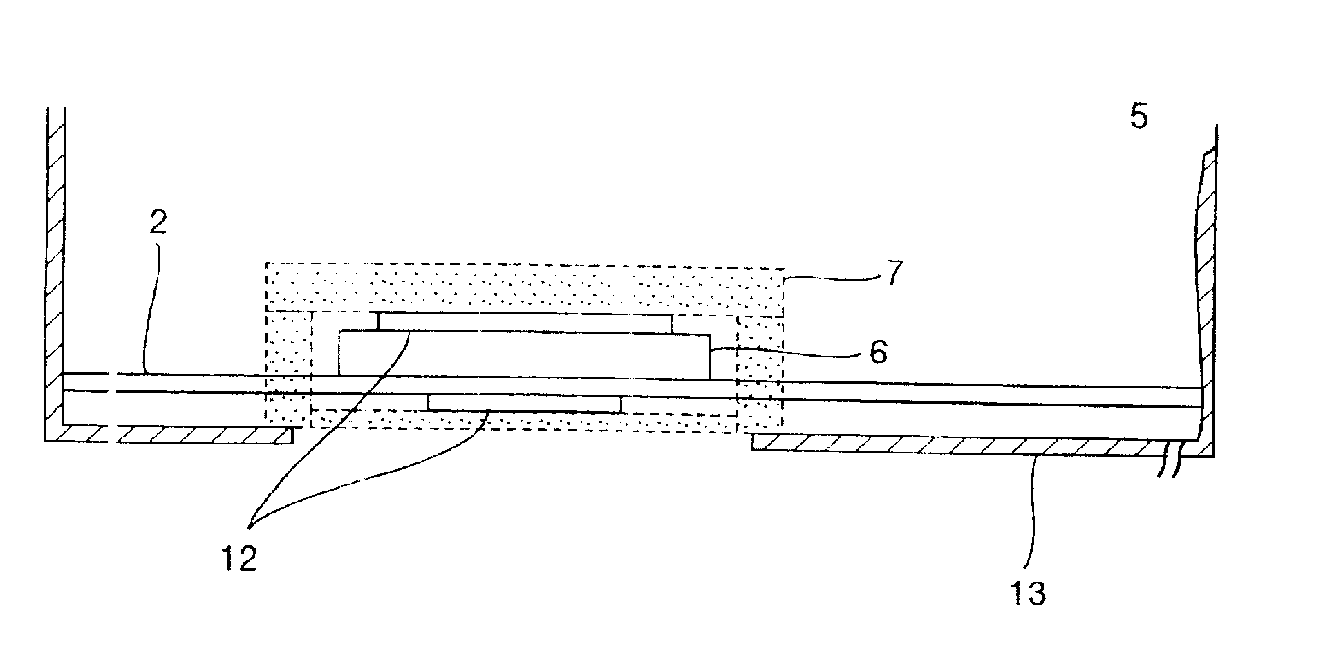
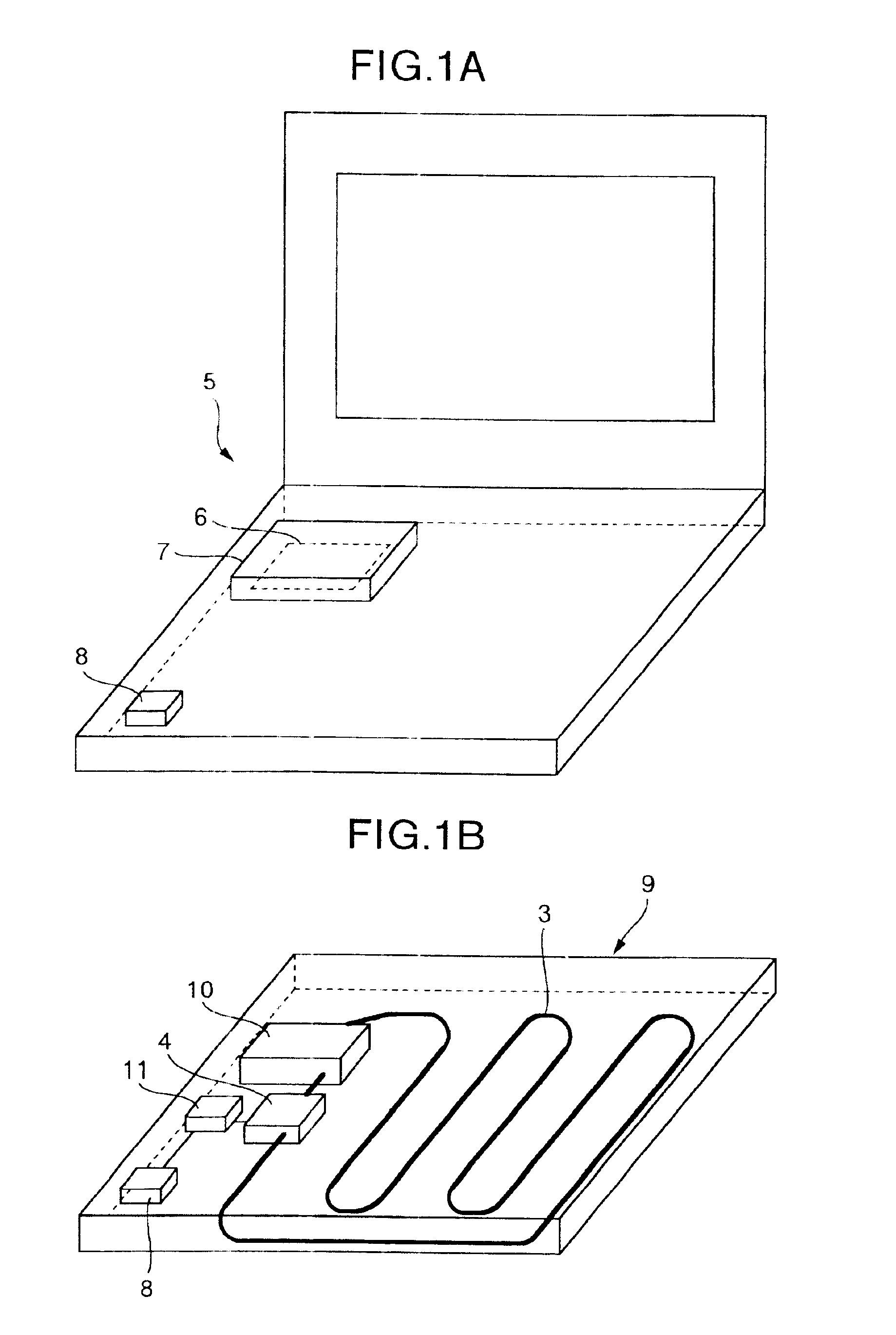
FIG. 1A is a schematic representation of a general structure of an information processing system or a personal computer in a first embodiment of the invention in which a cooling mechanism using liquid cooling method is employed. And FIG. 1B is a schematic representation of a general structure of a cooling unit of the personal computer shown in FIG. 1A.

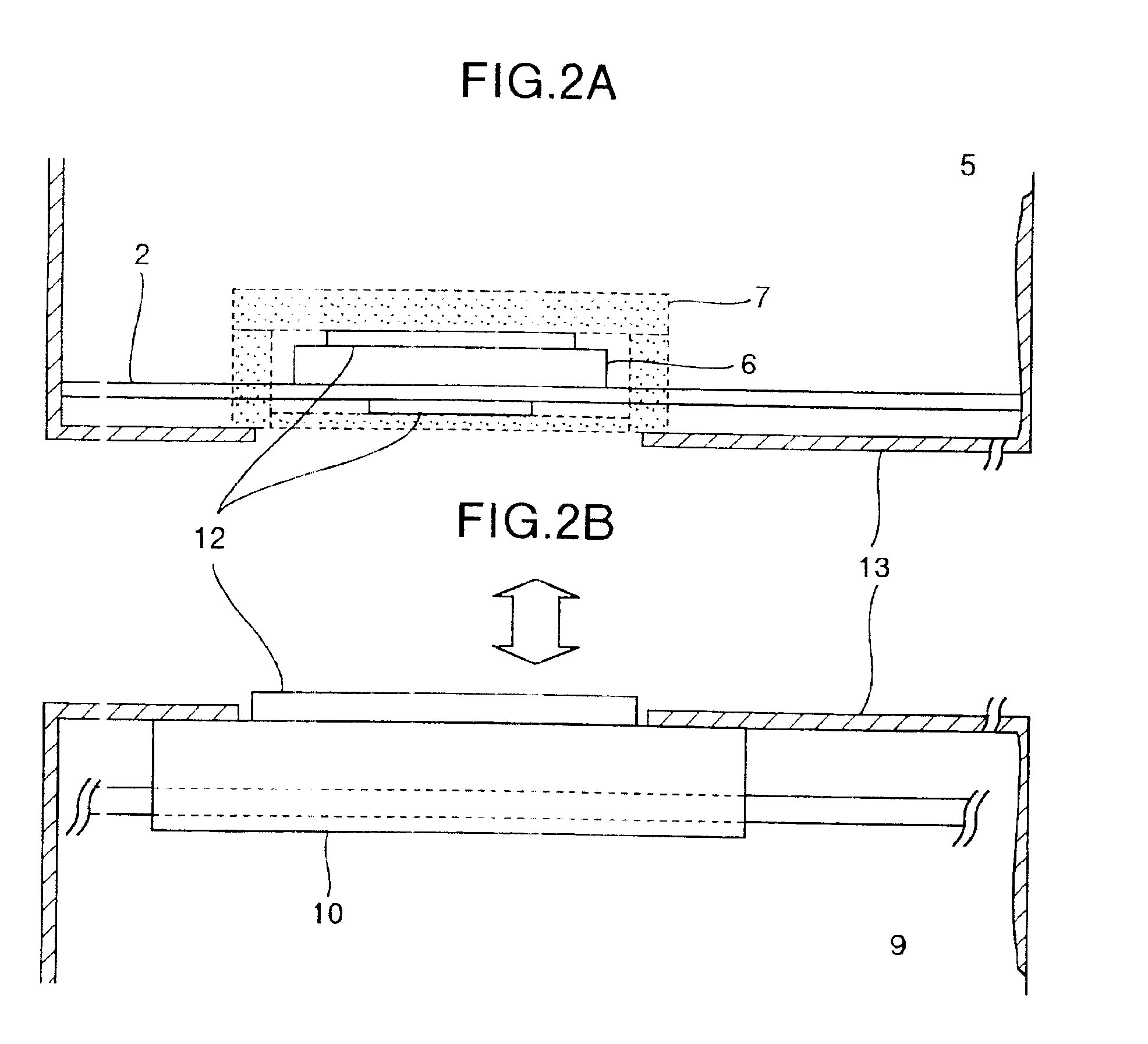
A shown in FIGS. 1A and 1B, the personal computer of the invention comprises a CPU 6, which is the main heat-generating part, a main body 5 of the personal computer, in which a display part is provided, and a cooling unit 9, which can be connected to the lower part of the main body 5 of the personal computer. Heat from the CPU 6 disposed in the main body 5 of the personal computer is transferred to a connection head 10 within a cooling unit 9 via a heat-receiving head 7. The connection head 10 is connected to a tube 3 which is arranged on the bottom surface of the cooling unit 9 in a zigzag form and filled with a cooling liquid. A pump...


PUM


Abstract

A personal computer provided with heat-generating parts such as a CPU, a cooling unit that releases the heat generated by the heat-generating part to the outside of the personal computer has a container structure so that the cooling liquid in the interior does not leak to the outside. Also, part of the container structure is provided with a heat connection part for receiving the heat transferred from the outside of the cooling unit. Furthermore, there is provided means of heat transfer for transferring the heat generated by the heat-generating part to the cooling unit, one end of this means of heat transfer being thermally connected to the heat connection part of the cooling unit and the other end thereof being thermally connected to the heat-generating part. This prevents troubles in the personal computer due to the moisture permeation of the cooling liquid of cooling unit and leakage of the cooling liquid. Also, disassembly and assembly is made easy by forming the cooling unit as a separate structure.

Description

BACKGROUND OF THE INVENTIONThe present invention relates to an information processing system or a personal computer and, more particularly, to a personal computer in which liquid cooling technology is used in the heat release mechanism of heat-generating parts.In the cooling of conventional information processing system such as personal computers, a metal plate or heat pipe is interposed between a heat-generating member within the personal computer and a metal frame wall, and the heat-generating member is thermally connected to the metal frame wall, whereby the heat generated by the heat-generating part is released through the metal frame wall. Furthermore, by installing a fan on the metal frame wall, the air in the personal computer is exhausted, whereby forced air cooling is performed.The main heat-generating part of an information processing system or a personal computer is the central processing unit (hereinafter referred to as a CPU) of the main part of the personal computer. D...

Claims


Application Information

Patent Timeline
Patent Type & Authority Patents(United States)
IPC IPC(8): G06F1/20H05K7/20G06F1/16
CPCG06F1/203
Inventor IGARASHI, TAKESHI
Owner MAXELL HLDG LTD
Learn More