
Polyimide film-laminated body

a polyimide film and laminated body technology, applied in the field of laminated bodies, can solve the problems of low peel strength, low peel strength of laminated bodies formed by metal vapor deposition or sputtering, and inability to achieve high adhesive strength with adhesives, etc., to achieve improved moisture permeation rate, improved surface adhesion, and high adhesive strength

Inactive Publication Date: 2009-03-12
UBE IND LTD
View PDF4 Cites 18 Cited by
  • Summary
  • Abstract
  • Description
  • Claims
  • Application Information

AI Technical Summary

Benefits of technology

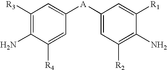
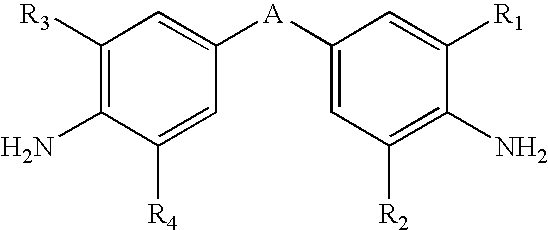
[0009]It is an object of the present invention to provide a polyimide film-laminated body which has reduced foaming and delamination during the high-temperature steps for production of the polyimide film-laminated body, due to an improved gas permeation rate and moisture permeation rate achieved by introduction of a diamine component with a specific structure, when using a 3,3′,4,4′-biphenyltetracarboxylic dianhydride as the essential tetracarboxylic dianhydride component.
[0014]In addition, the polyimide film-laminated body of the invention can produce a compact with improved surface adhesion and an improved moisture permeation rate.
[0015]The laminated body of the invention has high adhesive strength between the polyimide film and substrate and a high moisture permeation rate through the polyimide layer, and is therefore resistant to foaming or delamination at the adhesive interface during high-temperature treatment steps.

Problems solved by technology

However, it is not possible to achieve high adhesive strength with adhesives that are usually used in the field of electronics, while laminated bodies comprising metal layers formed by metal vapor deposition or sputtering have relatively low peel strength.
Yet their relatively low moisture permeation rates tend to result in foaming or delamination at the metal-polyimide interfaces of laminated bodies manufactured by casting methods.
In addition, a flexible printed wiring substrate has been proposed which comprises a metal film layer and a polyimide film layer formed by casting a polyamic acid solution composition obtained by polymerizing components containing an aliphatic tetracarboxylic anhydride and a diamine onto a metal substrate and imidizing it (see Japanese Unexamined Patent Publication No. 2004-358961), but excessive time is required for drying and imidization, and this results in poor productivity.

Method used


Image

  • Polyimide film-laminated body
  • Polyimide film-laminated body

Examples


examples 1-5

[0075]Solution 1 and solutions 2-6 were combined in a proportion such that the molar ratio of PPD as the diamine in the first solution and the diamine in the second solution was 90:10, and 1,2-dimethylimidazole was added to 2 mass % with respect to the polyamic acid. The resulting solution was coated onto the rough surface of a copper foil (SLP by Nippon Denkai, Ltd., 18 μm thickness) to a final film thickness of about 25 μm and heated at 135° C. for 3 minutes to form a solid film, after which it was anchored to a stainless steel frame and heated at 130° C. for 3 minutes and at 180° C. for 1 minute, raised in temperature to 450° C. over a period of 5 minutes and held at 450° C. for 2 minutes for heat treatment to obtain a polyimide copper foil laminated body. No foaming or delamination was observed in the obtained laminated body.

[0076]The 180° peel strength at the interface of the laminated body was measured to evaluate the adhesive strength. The copper foil of the laminated body wa...

examples 6-9

[0084]A polyimide copper foil laminated body was obtained in the same manner as Example 1, except that solution 1 and solution 3 were combined so that the diamine content in solution 3 was as listed in Table 2,1,2-dimethylimidazole was further added at 2 mass % with respect to the polyamic acid, and the resulting solution was coated onto the rough surface of a copper foil (SLP by Nippon Denkai, Ltd., 18 μm thickness) to a final film thickness of 25 μm. No foaming or delamination was observed in the obtained laminated body.

[0085]The 180° peel strength at the interface of the laminated body was measured to evaluate the adhesive strength. The copper foil of the laminated body was then etched with a 40% ferric chloride aqueous solution and the elastic modulus and breaking strength of the obtained polyimide film were measured.

[0086]The results are shown in Table 2.

example 10

[0089]A polyimide copper foil laminated body was obtained in the same manner as Example 2, except that coating was to a final film thickness of 15 μm. No foaming or delamination was observed in the obtained laminated body.

[0090]The results are shown in Table 2.

TABLE 2DiaminePolyimideTen-content oflayerBreak-sile180°Foam-polyimidethick-ingmodu-Peeling / layernessstrengthlusstrengthdelam-Example(mol %)(μ)(MPa)(GPa)(kg / cm)inationExampleSolution 3254307.90.6none65%ExampleSolution 3253707.41.15none715%ExampleSolution 3253407.21.2none820%ExampleSolution 3253306.81.2none930%ExampleSolution 3154107.81.1none1010%Compara-Solution 3251134.4nonetive50%Example3


PUM

PropertyMeasurementUnit
Thicknessaaaaaaaaaa
Elastic modulusaaaaaaaaaa

Abstract

A polyimide film-laminated body is composed of a metal layer and an aromatic polyimide layer formed by casting a polyamic acid solution composition, comprising 3,3′,4,4′-biphenyltetracarboxylic dianhydride as an essential tetracarboxylic dianhydride component and with introduction of a specific diamine component, onto a metal foil. The polyimide film-laminated body has an excellent gas permeation rate and moisture permeation rate, with heat resistance, a high elastic modulus and a low linear expansion coefficient, and with reduced foaming and delamination during the high-temperature steps for formation of the laminated body.

Description

TECHNICAL FIELD[0001]The present invention relates to a laminated body comprising a metal layer and an aromatic polyimide layer formed from an aromatic polyamic acid solution composition that is to be used as a dope solution for formation of an aromatic polyimide film layer, and the laminated body can be suitably used as a copper-clad wiring substrate for manufacture of a printed circuit board which is to be used in the electronic and electrical industries, or which can also be used as a different kind of electronic material such as a heater, radiator plate, thermal response element, hard disk suspension or the like, depending on the type of metal material. More specifically, the invention relates to a polyimide film-laminated body comprising a metal layer and an aromatic polyimide layer formed by casting a polyamic acid solution composition, wherein a tetracarboxylic dianhydride consisting of 3,3′,4,4′-biphenyltetracarboxylic dianhydride as an essential component is the starting te...

Claims


Application Information

Patent Timeline
IPC IPC(8): B32B15/08
CPCB32B15/08B32B15/20C08G73/1067H05K1/0346Y10T428/266H05K2201/0355H05K2203/0759B32B27/281B32B2457/08H05K3/389Y10T428/31678Y10T428/31681
Inventor MURAKAMI, MASATOYAMAGUCHI, HIROAKI
Owner UBE IND LTD
Learn More