Method for laminating and patterning carbon nanotubes using chemical self-assembly process

a carbon nanotube and chemical self-assembly technology, applied in the direction of photosensitive materials, instruments, photomechanical equipment, etc., can solve the problems of inability to anticipate sufficient electrical conductivity on the surface of carbon nanotubes, low surface density of carbon nanotubes, and arranging carbon nanotubes on a substra

Active Publication Date: 2005-11-01
SAMSUNG ELECTRONICS CO LTD
View PDF6 Cites 20 Cited by
  • Summary
  • Abstract
  • Description
  • Claims
  • Application Information

AI Technical Summary

Benefits of technology

[0006]It is a feature of the present invention to provide a simple method of producing a carbon nanotube pattern by formin

Problems solved by technology

Conventional methods for arranging carbon nanotubes on a substrate are limited to a monolayer structure of carbon nanotubes, and thus the surface density of carbon nanotubes is low.
For this reason, a sufficient electrical conductivity on the surface of carbon nanotubes cannot be anticipated.
In addition, because conventional patterning methods depend on simple adsorption of carbon nanotubes,

Method used


Image

  • Method for laminating and patterning carbon nanotubes using chemical self-assembly process
  • Method for laminating and patterning carbon nanotubes using chemical self-assembly process
  • Method for laminating and patterning carbon nanotubes using chemical self-assembly process

Examples


example 1

Purification of Carbon Nanotubes

[0087]5 g of carbon nanotubes were dispersed in 700 ml of HNO3 aqueous solution (2.6M) in a 2 L flask equipped with a reflux condenser, and then refluxed at 100° C. for 48 hours. The resulting mixture was centrifuged at 2000 rpm for 30 minutes to separate precipitates and a supernatant of acid solution. The supernatant was removed. Then, the precipitates were dispersed in distilled water, and centrifuged again to remove a supernatant. These series of processes were repeated three times or more. The finally washed precipitates were dispersed in an aqueous solution containing 5% by weight of Triton X-100, and the dispersion was adjusted to a pH of 10 or higher using sodium hydroxide (NaOH). Subsequently, the resulting mixture was subjected to a sonication process for 10 hours, and thereafter 10 g of hydrochloric acid (HCl) was added to precipitate single wall carbon nanotubes. The solution was centrifuged at 2,000 rpm for 30 minutes to separate an aqueo...

example 2

Cutting of Carbon Nanotubes

[0088]1 g of the carbon nanotubes obtained from Example 1 was sonicated in 100 ml of an acidic mixture of sulfuric acid and nitric acid (3:1 (v / v)) for 24 hours using a sonicator. The resulting solution was poured into 500 ml of distilled water, passed through a polycarbonate filter with a pore size of 0.1 μm, and dried under reduced pressure to fabricate carboxylated carbon nanotubes.

example 3

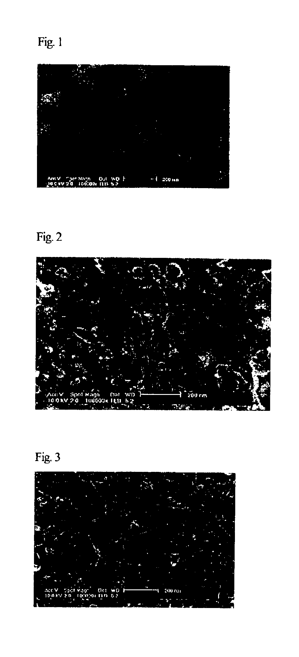
Formation of Carbon Nanotube Monolayer Structure

[0089]A glass substrate was immersed in an alcoholic solution of 0.1% (v / v) aminopropyltriethoxysilane, and the alcoholic solution was stirred at room temperature for 5 minutes. The glass substrate was washed by immersing it in ethyl alcohol three times, and dried in a vacuum oven at 120° C. for 20 minutes. After the dried glass substrate was held under argon gas atmosphere for 12 hours, it was immersed in DMF and sufficiently washed with dichloromethane. Next, 2 mg of the carboxylated carbon nanotubes obtained from Example 2 were dispersed in 200 ml of DMF using a sonicator. To the dispersion of the carbon nanotubes, 2 g of N,N-diisopropylethylamine (hereinafter, referred to as ‘DIEA’) was added dropwise followed by stirring for 10 minutes. Subsequently, 50 ml of DMF dissolving 2.5 g of O-(7-azabenzotriazol-1-yl)-N,N,N′,N′-tetramethyluronium hexafluorophosphate (hereinafter, referred to as ‘HATU’) was added to the dispersion of the ca...


PUM


Abstract

A method for forming a pattern of carbon nanotubes includes forming a pattern on a surface-treated substrate using a photolithographic process, and laminating carbon nanotubes thereon using a chemical self-assembly process so as to form the carbon nanotubes in a monolayer or multilayer structure. A monolayer or multilayer carbon nanotube pattern may be easily formed on the substrate, e.g., glass, a silicon wafer and a plastic. Accordingly, the method can be applied to form patterned carbon nanotube layers having a high conductivity, and thus will be usefully utilized in the manufacturing processes of energy storages, for example, solar cells and batteries, flat panel displays, transistors, chemical and biological sensors, semiconductor devices and the like.

Description

BACKGROUND OF THE INVENTION[0001]1. Field of the Invention[0002]The present invention relates to a method for laminating and patterning carbon nanotubes using a chemical self-assembly process, and more particularly to a method for forming a pattern of carbon nanotubes, comprising forming a pattern on a surface-treated substrate using a photolithographic process, and laminating carbon nanotubes thereon using a chemical self-assembly process so as to form the carbon nanotubes in a monolayer or multilayer structure.[0003]2. Description of the Related Art[0004]Since carbon nanotubes were first discovered in 1991 by Dr. Iijima of Meijo University in Japan, who engaged in developing electron microscopes, many studies on carbon nanotubes have been undertaken. Carbon nanotubes have such a structure that a graphite plate is rolled into a tube of which the diameter is typically within the range of 1 to 20 nm. Graphite is very unique in the arrangement of carbon atoms and has a strong and flat...

Claims


Application Information

Patent Timeline
IPC IPC(8): G03F7/40G03F7/16G03F7/039B82B3/00B82Y30/00B82Y40/00C01B31/02G03F1/00H01B13/00
CPCB82Y10/00B82Y30/00G03F7/0392G03F7/165G03F7/168G03F7/40Y10S977/842G03F1/00G03F1/68B82B3/00B82B1/00
Inventor JUNG, MYUNG SUPPARK, JONG JINJUNG, SUNG OUKSEO, SEUNG JOOKOO, BON WON
Owner SAMSUNG ELECTRONICS CO LTD
Why Eureka
Try Eureka