Laser diode with a spatially varying electrostatic field frequency converter

Active Publication Date: 2005-03-08
LASER OPERATIONS
View PDF7 Cites 4 Cited by
  • Summary
  • Abstract
  • Description
  • Claims
  • Application Information

AI Technical Summary

Problems solved by technology

There are unfortunately no practical laser diodes in this wavelength region.
Diodes using Quantum Cascade designs have been dem

Method used


Image

  • Laser diode with a spatially varying electrostatic field frequency converter
  • Laser diode with a spatially varying electrostatic field frequency converter

Examples


Embodiment Construction

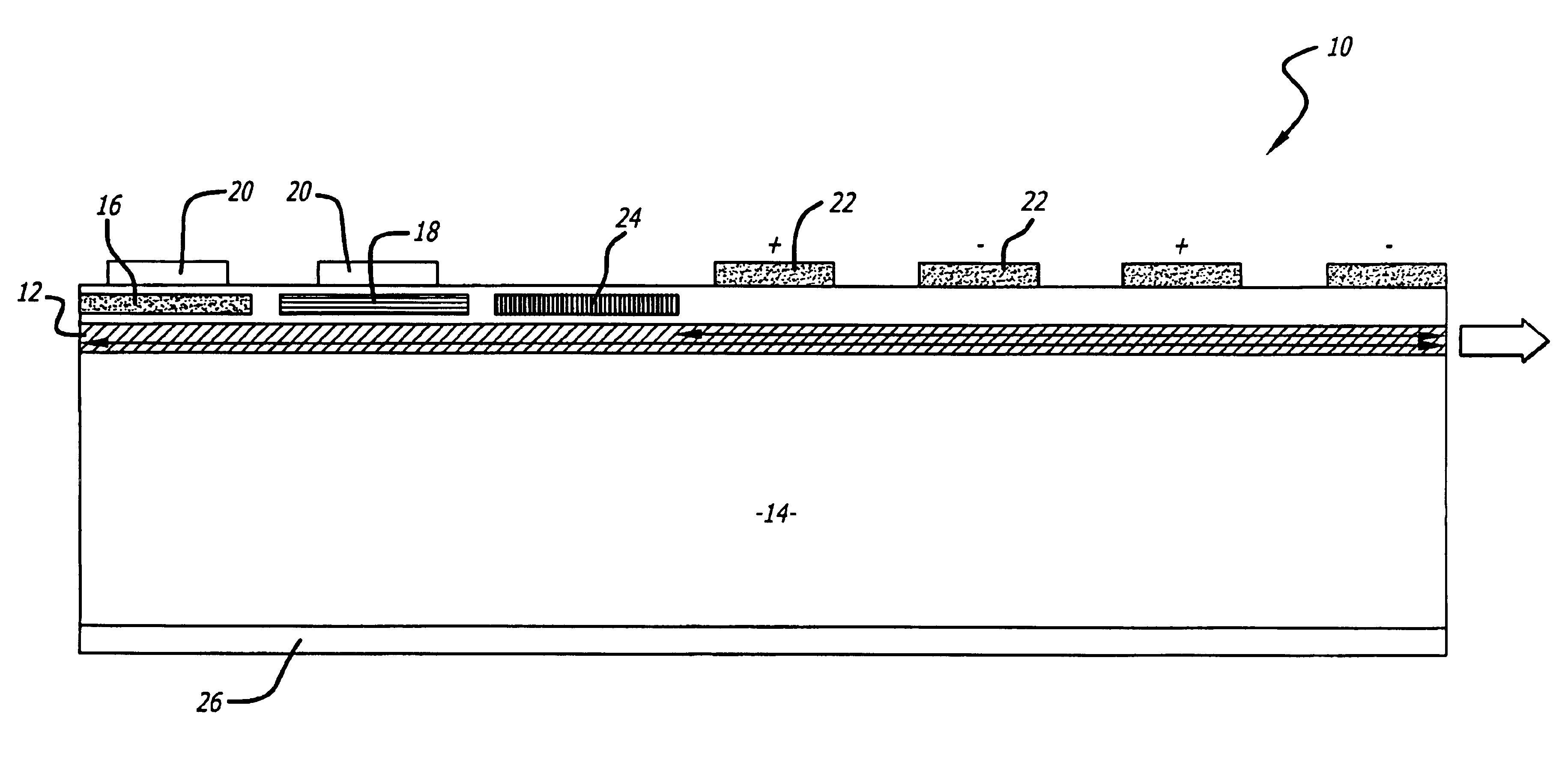
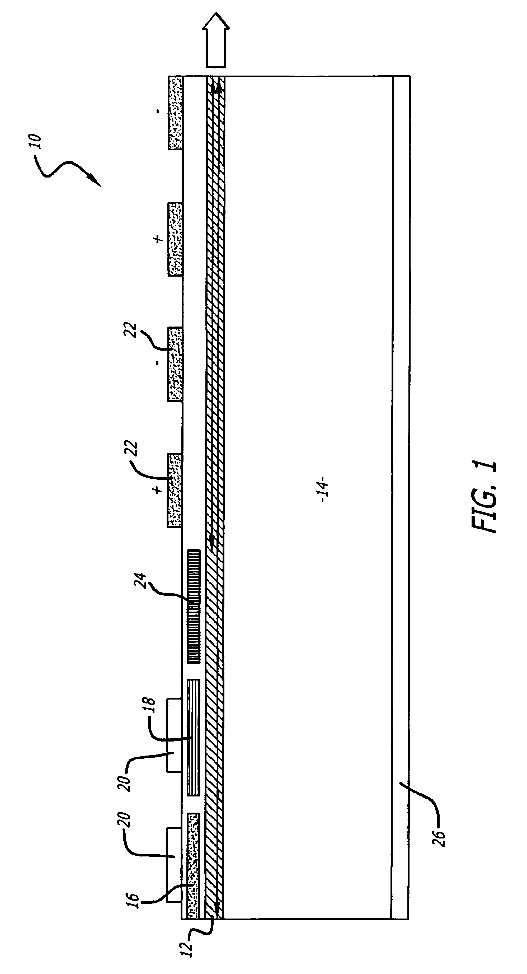
Disclosed is a semiconductor diode laser that generates light at wavelengths longer than conventional diode lasers. The laser includes a first gain element that generates a first “pump” laser beam having a first frequency and a second gain element that generates a second “pump” laser beam having a second frequency. A nonlinear frequency conversion section mixes the two beams to generate a third co-propagating optical beam at the difference frequency. To improve efficiency, the frequency conversion section is furnished with an array of charged electrodes that spatially modulate the nonlinear susceptibility and phase-match the three beams.

FIG. 1 shows a laser 10 that generates a beam of light typically at mid-infrared frequencies between 2 and 10 μm. Laser 10 consists of semiconductor optical waveguide 12 and adjacent optical gain sections 16 and 18 fabricated on top of semiconductor substrate 14. Optical waveguide 12 and gain sections 16 and 18 are fabricated from epitaxial multi-lay...


PUM


Abstract

A semiconductor diode laser that generates light at wavelengths longer than conventional diode lasers. The laser includes a first gain element that generates a first “pump” laser beam having a first frequency and a second gain element that generates a second “pump” laser beam having a second frequency. A nonlinear frequency conversion section mixes the two beams to generate a third co-propagating optical beam at the difference frequency. To improve efficiency, the frequency conversion section is furnished with an array of charged electrodes that spatially modulate the nonlinear susceptibility and phase-match the three beams.

Description

BACKGROUND OF THE INVENTION1. Field of the InventionThe subject matter disclosed generally relates to the field of semiconductor lasers.2. Background InformationConventional laser diodes, which are fabricated from III-V compound semiconductors such as GaAlAs, InGaAlP and InGaAsP operate at wavelengths between 0.4 and 1.6 μm. Longer wavelengths in the mid-infrared range between 2 and 10 μm are required for important applications, including:Optical communications in the open atmosphere, which are highly vulnerable to scattering by fog and rain at conventional diode wavelengths shorter than 2 μm. By contrast, the atmosphere is much more transparent to wavelengths around 10 μm, where attenuation through fog can be as much as 150 db / km lower.Measures to protect civilian and military aircraft from attack by shoulder-fired missiles, which use transmission of optical pulses in the 2 to 4.5 μm band to confuse their heat-seeking guidance systems.The presence of chemical weapons such as nerve ...

Claims


Application Information

Patent Timeline
IPC IPC(8): H01S3/08H01S3/10H01S5/00G02F1/35G02F1/355H01SH01S1/02H01S5/026H01S5/06H01S5/10H01S5/12
CPCB82Y20/00G02F1/3534H01S5/0604H01S5/06258H01S1/02G02F1/3556G02F2001/3546H01S5/4087H01S5/1025H01S5/18G02F1/3546
Inventor UNGAR, JEFFREY E.LAMMERT, ROBERT M.
Owner LASER OPERATIONS
Why Eureka
Try Eureka