System and method for detecting modifications of video signals designed to prevent copying by traditional video tape recorders

a video signal and video system technology, applied in the field of video system anti-copying process of video tape recorder, can solve the problems of difficult locking of the television receiving equipment to the signal, picture breakage, and slight inaccurate timing, and achieve the effect of removing noise and not eliminating anti-copying artifacts

Inactive Publication Date: 2005-03-08
CONEXANT SYST INC
View PDF9 Cites 18 Cited by
  • Summary
  • Abstract
  • Description
  • Claims
  • Application Information

AI Technical Summary

Benefits of technology

The present invention provides a system and method for detecting whether a video signal is modified by a video-tape-recorder-design based anti-copying process. The video signal is sampled and a portion thereof, within which anti-copying artifacts may be encoded, is selected. This selected portion of the video signal is then filtered to ...

Problems solved by technology

Numerous problems can result from even slightly inaccurate timing.
Errors in the pulse widths can lead to picture break up, and errors in the rise and fall times can make it difficult for the television receiving equipment to lock to the signals.
However, this same technology now allows a single inexperienced person with a single copy of a video program to create numerous unauthorized copies of a copyrighted work, thereby substantially reducing the legitimate demand for a particular work.
Without anti-copying systems in place, copyright holders run the risk of losing control of their works with a single broadcast or release on videocassette.
These waveforms prevent copying of the original by adding artifacts which have little effect on electronic devices, such as televisions, but which tend to confuse mec...

Method used


Image

  • System and method for detecting modifications of video signals designed to prevent copying by traditional video tape recorders
  • System and method for detecting modifications of video signals designed to prevent copying by traditional video tape recorders
  • System and method for detecting modifications of video signals designed to prevent copying by traditional video tape recorders

Examples


Embodiment Construction

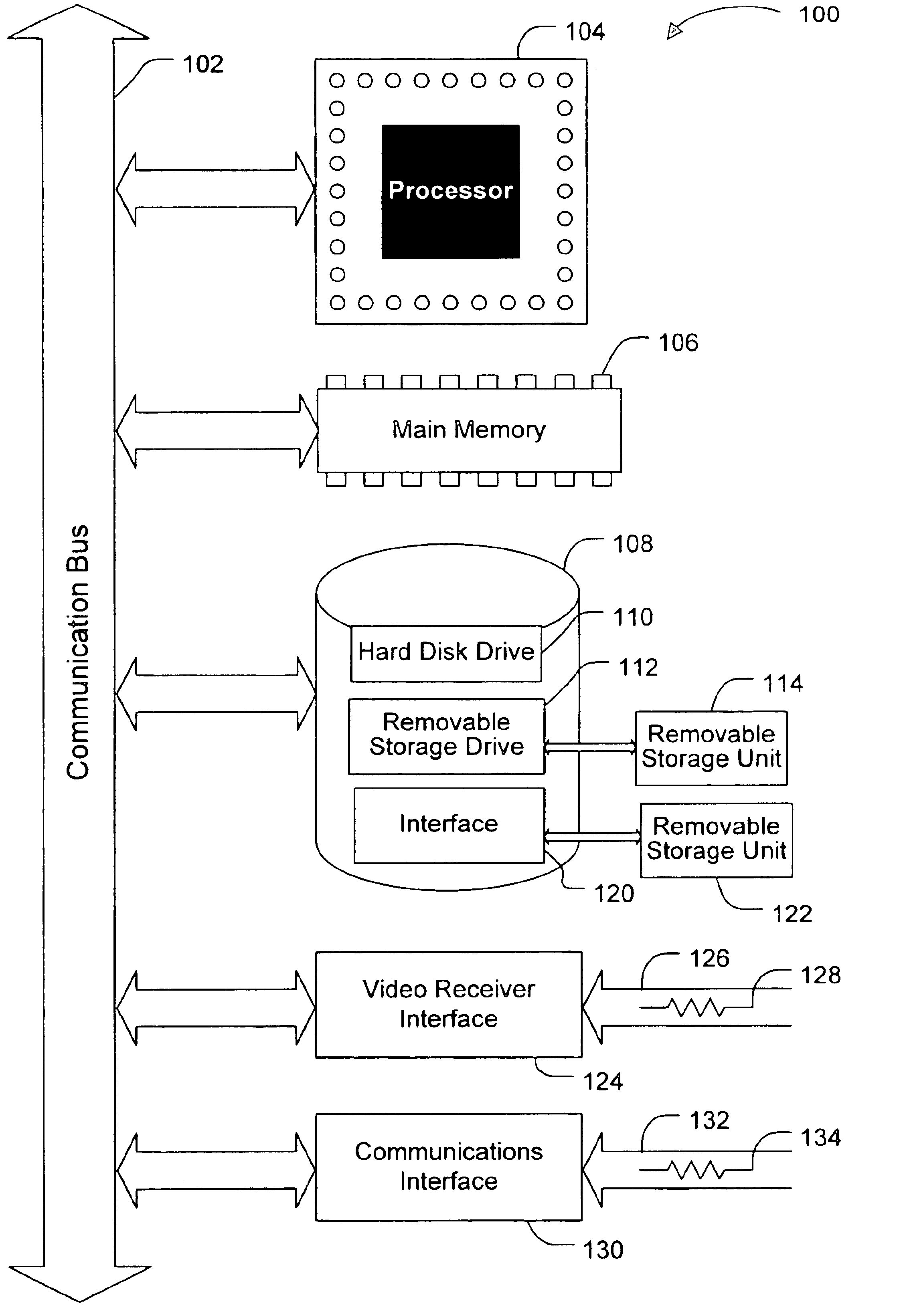
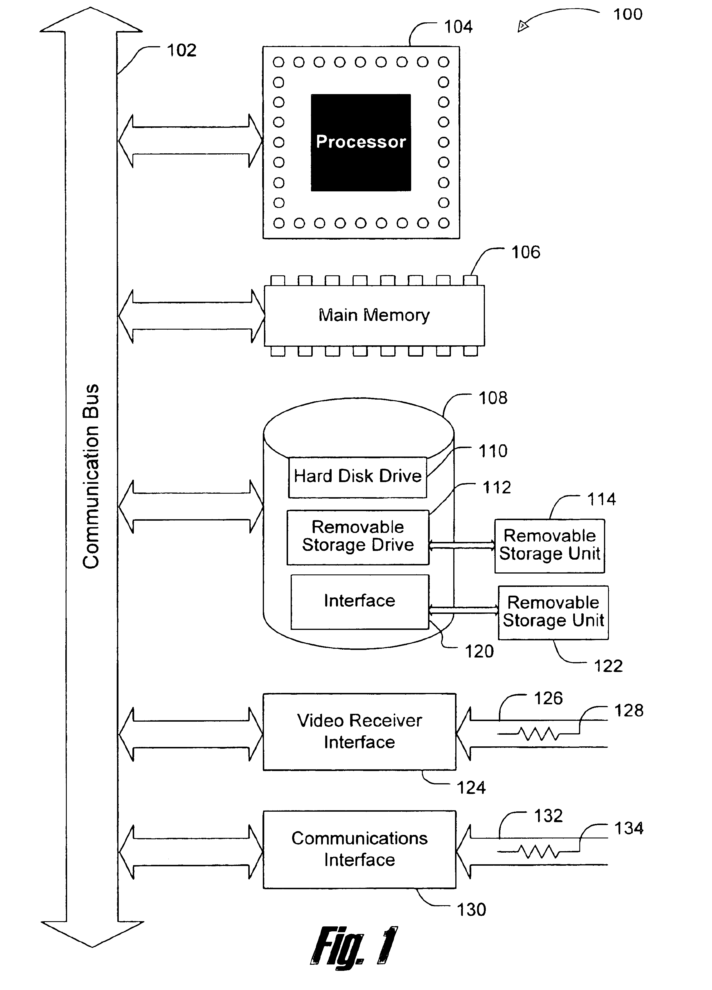
The present invention is directed toward a system and method for applying traditional video-tape-recorder-design based anti-copying processes to modern digital video recording systems. The present invention is disclosed and described herein in terms of a video capture card coupled with a general purpose personal computer. However, after reading this description it will become apparent to one skilled in the relevant art(s) how to implement the invention in alternative embodiments and alternative applications. For example, alternative embodiments include digital VCRs, handheld digital cameras, personal digital assistants (PDAs) and next-generation wireless handsets. As such, the description of this example embodiment should not be construed to limit the scope and breadth of the present invention.

FIG. 1 is a block diagram illustrating an example computer system in which elements and functionality of the invention are implemented according to one embodiment of the present invention. The...


PUM


Abstract

A system and method for detecting whether a video signal is modified by a video-tape-recorder-design based anti-copying process. A proper portion of the video signal is identified and filtered, and potential anti-copying artifacts in the filtered signal are counted by comparing the filtered output against a threshold derived from the video-tape-recorder-design based anti-copying process. By cross-correlating the number of potential anti-copying artifacts, found on multiple scan lines across multiple frames, with an expected minimum range and/or number of anti-copying artifacts derived from the video-tape-recorder-design based anti-copying process, anti-copying modifications of the video signal are detected. In this fashion, traditional video-tape-recorder-design based anti-copying processes are applied to modem digital video recording systems.

Description

BACKGROUND OF THE INVENTION1. Field of the InventionThe present invention relates generally to the field of video-tape-recorder-design based anti-copying processes for video systems, and more particularly to the application of those processes to digital video recording systems.2. Related ArtTelevisions utilize cathode ray tubes (CRTs) to display video images. CRTs have electron guns that produce an electron beam. The beam is attracted to phosphors on the face of the CRT, activating the phosphors and causing them to emit light. The electron beam begins at the top left of the CRT and scans from left to right across the screen, illuminating pixels (which are comprised of the activated phosphors) in the process. Hence, the electron beam effectively draws horizontal lines of video, one pixel at a time.The horizontal scan rate is the number of horizontal lines drawn per second by the electron beam generated by the electron gun in a video display. Television broadcast standards specify exa...

Claims


Application Information

Patent Timeline
IPC IPC(8): H04N5/913
CPCH04N5/913H04N2005/91314
Inventor MULLER, STEPHEN C.
Owner CONEXANT SYST INC
Why Eureka
Try Eureka