Flexible wind abatement system

a technology of wind abatement system and flexible structure, which is applied in the direction of walls, roofs, ceilings, etc., can solve the problems of unsightly and difficult-to-mount reinforcing bars, loud, disturbing and often frightening bangs of inhabitants being protected, and achieves convenient use, easy protection, and light weight

Inactive Publication Date: 2005-03-15
ARMOR SCREEN
View PDF27 Cites 104 Cited by
  • Summary
  • Abstract
  • Description
  • Claims
  • Application Information

AI Technical Summary

Benefits of technology

This invention contemplates the use of a flexible barrier, preferably a reasonably transparent, woven synthetic textile that is able to satisfy stringent testing requirements. Knitted or extruded material can be an alternative if the material itself meets the criteria described later herein. The use of this invention allows very large areas with spans of greater than 25 feet to be covered with ease. Thus most window groupings, even several stories of a building, could

Problems solved by technology

These devices are typically expensive to purchase, cumbersome, made from stiff, heavy material such as steel and aircraft quality aluminum alloy or occasionally plastic with reinforcing.
Many require unsightly and difficult-to-mount reinforcing bars at multiple locations.
Further, these known shutters are usually opaque, preventing light from entering a shuttered area and preventing an inhabitant from seeing out.
Missiles, even small not potentially damaging missiles, striking these heretofore known shutters create a loud, often frightening bang that is disturbing to inhabitants being protected.
As a result of said standards, many undesirable aspects of the heretofore known shutters have been acerbated.
They have become more cumbersome, more bulky, heavier, more expensive, more difficult to store, and remain generally opaque and noisy when impacted.
To incorporate sufficient strength to meet said requirements, weight and bulk become a problem over six feet in span.
This makes protecting large windows, for example, or groupings of windows, with the heretofore known devices cumbersome

Method used


Image

  • Flexible wind abatement system
  • Flexible wind abatement system
  • Flexible wind abatement system

Examples


example

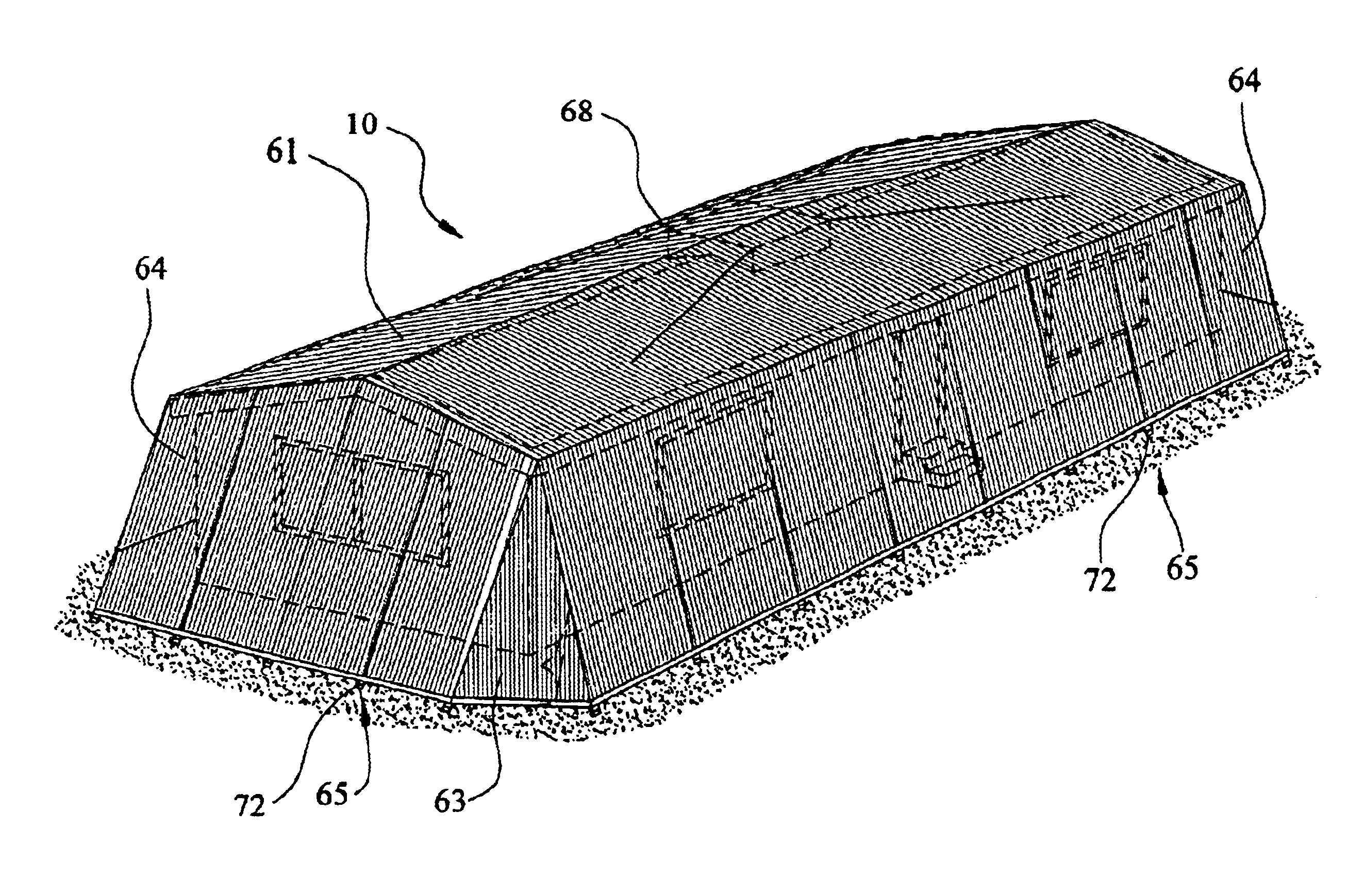
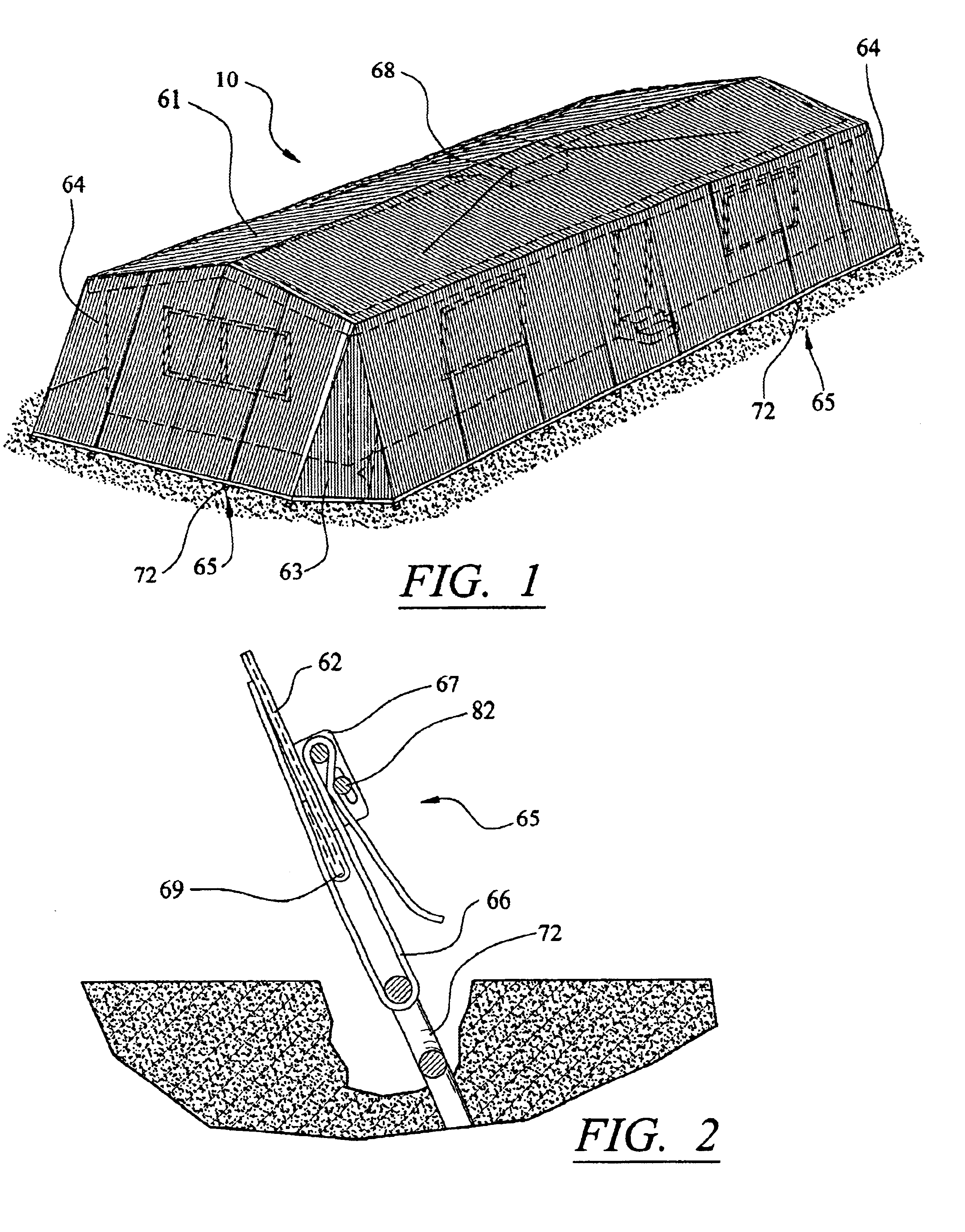
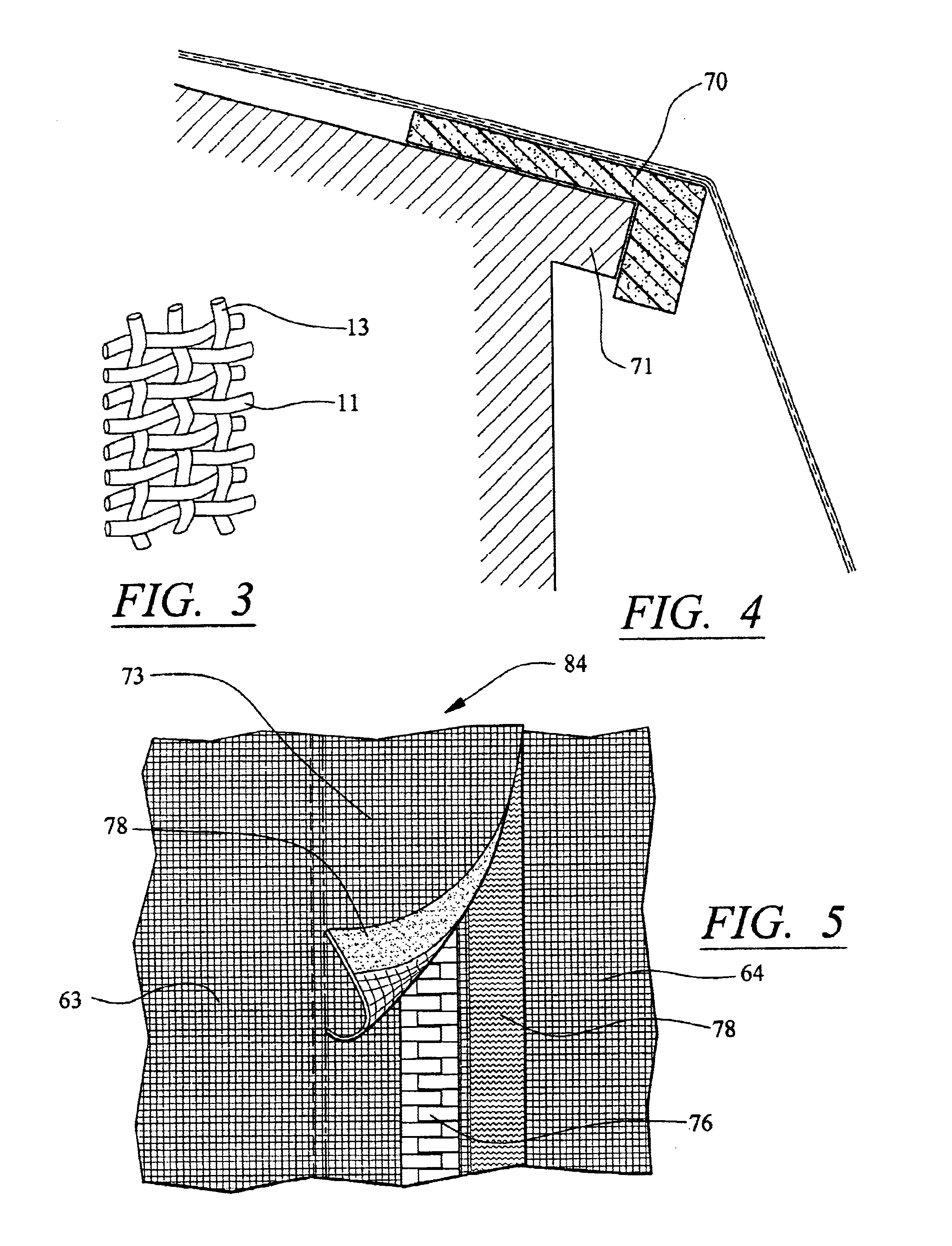
The preferred embodiment is used as an example to demonstrate this formula. The preferred embodiment is a polypropylene, woven monofilament geotextile. The individual filaments are woven into a basket weave network and calendered so that the filaments retain dimensional stability relative to each other. This geotextile is resistant to ultra violet degradation and to biological and chemical environments normally found in soils. This fabric is often used as the mat for outdoor trampolines and is intended to be very resistant to weathering. The fabric is known to stretch a maximum of 21% prior to failure and requires a force of 675 psi to fail.

1. The present test that was originally legislated by Dade County Florrida and may become the standard in the industry, requires the barrier to withstand a force of only 61.3 psi. Consequently the fabric meets and exceeds the first requirement of strength.1. The stretch factor calculation is (test load / maximum load×% stretch at maximum load=stret...


PUM


Abstract

A device for protection of property against high winds comprising a flexible material of predetermined strength and stretch characteristics, and in the form of a panel or several panels, utilized to protect the side of a structure including its windows and doors from the strong winds and debris impacts occurring during a hurricane. The device is anchored in a manner to space it out from the area being protected according to formula provided, and can safely dissipate substantial impacting energy. The preferred embodiment attaches to an overhanging eave and the ground below protecting in addition to the windows and doors, plantings, outdoor furniture, decorative shutters, downspouts, and such as are enclosed behind the barrier. Several methods of storage and deployment of said curtain are described including rolling, sliding, and converting to awning. The barrier has the added feature of acting as a tie down in certain applications.

Description

TECHNICAL FIELDThis invention relates to the protection of property against high winds and, in particular, to a flexible protective barrier device for securing property from damage from the wind itself and from the impact of foreign objects carried by wind as occasioned by hurricanes, tornadoes and the like.BACKGROUND ARTAs is known by one skilled in the art of protecting buildings and the like from damage caused by missile-like objects that are occasioned by the heavy winds of hurricanes or tornadoes, there are commercially available variations of hurricane protective devices, often called shutters, that fasten immediately over the frangible area to be protected. These devices are typically expensive to purchase, cumbersome, made from stiff, heavy material such as steel and aircraft quality aluminum alloy or occasionally plastic with reinforcing. Many need to be manually connected and then removed and stored at each threat of inclement weather. Many require unsightly and difficult-...

Claims


Application Information

Patent Timeline
IPC IPC(8): E04H9/14E04B1/00
CPCE04H9/14E04B2001/2684Y10S160/01Y02A50/00
Inventor GOWER, TED
Owner ARMOR SCREEN
Why Eureka
Try Eureka