
System and method for controlling ignition in internal combustion engines

a technology of internal combustion engine and ignition timing, which is applied in the direction of combustion engine, fuel injection apparatus, charge feed system, etc., can solve the problems of local combustion air to fuel ratio that cannot be controlled, local hot spots, and relatively high production of nitrogen oxides and other regulated pollutants, so as to stabilize the ignition timing of an hcci engine and increase the control options available.

Inactive Publication Date: 2005-03-15
GE GLOBAL SOURCING LLC
View PDF6 Cites 16 Cited by
  • Summary
  • Abstract
  • Description
  • Claims
  • Application Information

AI Technical Summary

Benefits of technology

It would be desirable to stabilize ignition timing of an HCCI engine by increasing the control options available to control ignition timing thereof.
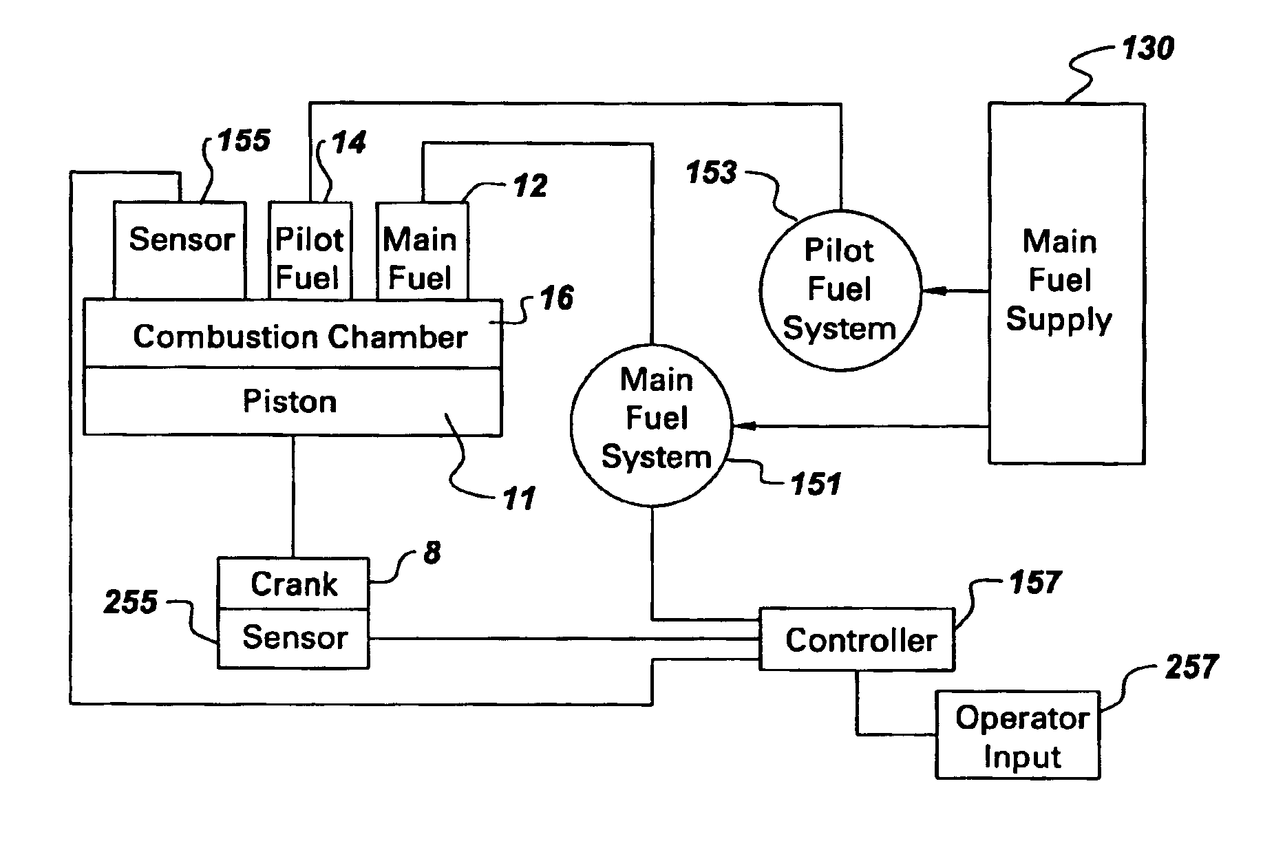
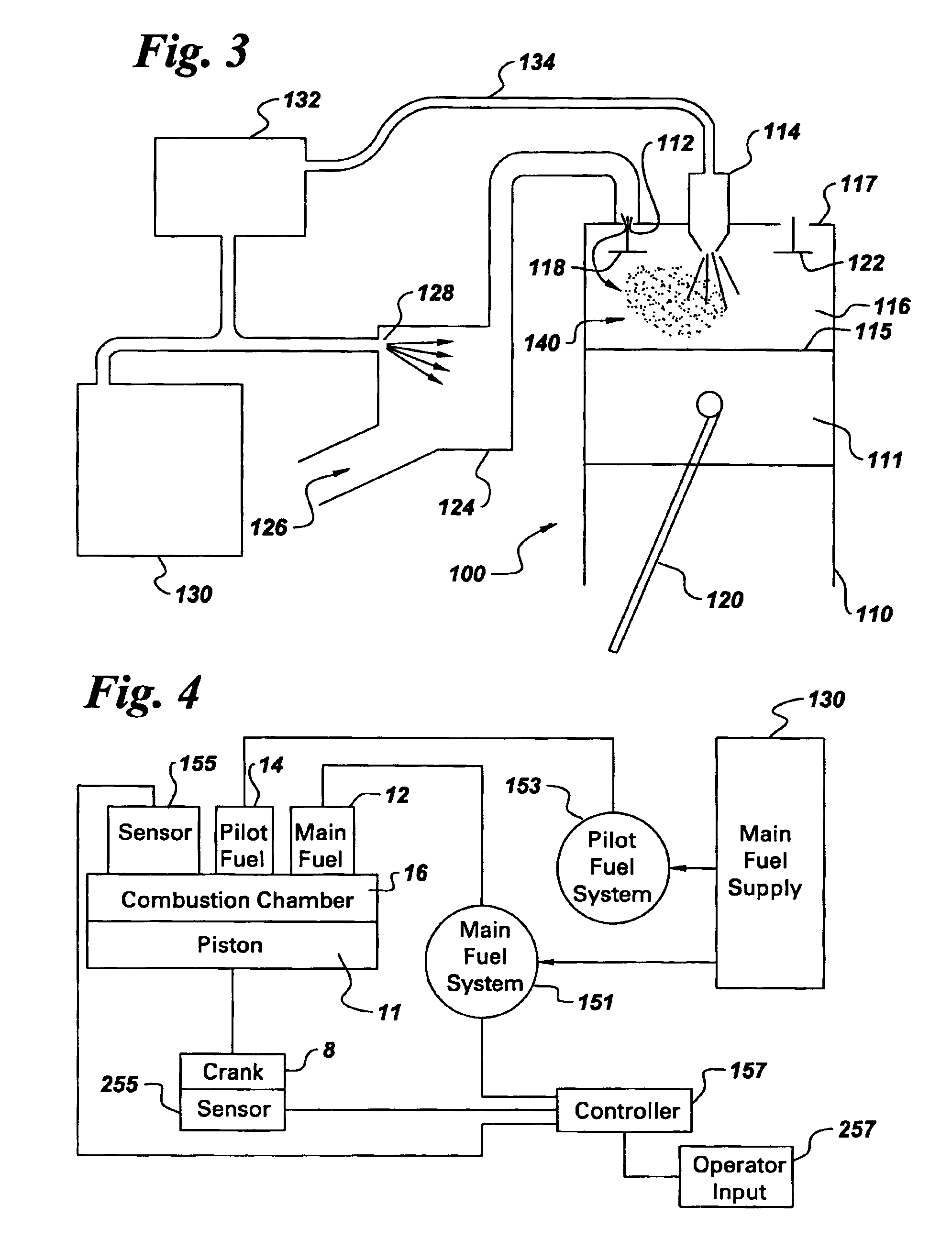
In accordance with another embodiment of the present invention, a diesel locomotive internal combustion engine comprising at least two cylinders, each having a reciprocating piston operatively connected to a crank and a combustion chamber, also comprising means for separately injecting a primary main fuel and a high combustion auxiliary pilot fuel into the combustion chambers of an internal combustion diesel engine comprises: a processing system in fluid communication with the main fuel, a portion of the main fuel flowing to the engine is diverted to said processing system, said processing system configured to process said portion of the main fuel to increase ignition sensitivity thereof forming the pilot fuel; a means to introduce the main fuel into the combustion chamber; and a means to introduce the pilot fuel to control ignition of the main fuel.

Problems solved by technology

However, the local combustion air to fuel ratio cannot be controlled.
This results in local hot spots and relatively high production of nitrogen oxides and other regulated pollutants.
This lower compression ratio results in lower cycle efficiency.
This reduces local hot spots and lowers the production of nitrogen oxides and other regulated pollutants.
However, HCCI engines rely on autoignition of their air-fuel (A / F) mixture and are difficult to control ignition thereof during compression.

Method used


Image

  • System and method for controlling ignition in internal combustion engines
  • System and method for controlling ignition in internal combustion engines
  • System and method for controlling ignition in internal combustion engines

Examples


Embodiment Construction

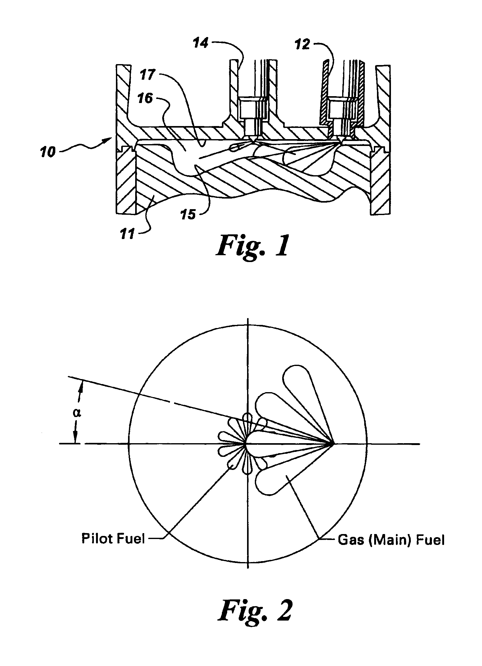
Disclosed herein is an additional control technique to modulate ignition timing within an engine, particularly HCCI engines, by introducing a main fuel which is hard to ignite in an A / F mixture during an intake stroke and introducing a pilot fuel more flammable than the main fuel at a desired point in the engine cycle. In this manner, the introduction of pilot fuel during compression of the main fuel into the chamber immediately ignites the small portion of pilot fuel upon entry into the combustion chamber as a result of the heat created by compression of the main fuel A / F mixture. The ignition of the pilot fuel causes ignition of the harder to ignite main fuel. The main fuel and pilot fuel are both obtained from a single fuel supply where the pilot fuel is an in situ reformed main fuel forming a lighter hydrocarbon based pilot fuel which is easier to ignite compared to the heavier hydrocarbon based main fuel.

FIG. 1 depicts the components of a typical combustion chamber of a cylinde...


PUM


Abstract

Ignition of a main fuel in an internal combustion engine having at least one cylinder having a combustion chamber is accomplished by diverting a portion of the main fuel to a processing system; processing said portion of the main fuel to increase ignition sensitivity thereof and form a pilot fuel; introducing the main fuel into the combustion chamber; and introducing said pilot fuel to control ignition of the main fuel.

Description

BACKGROUND OF THE INVENTIONThe invention relates generally to a system and method for controlling ignition in a homogeneous charge compression ignition (HCCI) engine by injecting a pilot fuel in conjunction with a main fuel. The system and method of this invention may be used to advantage in diesel fuel engines, and especially locomotive engines, as well as any other reciprocating engine.Diesel engines efficiently convert the latent heat of hydrocarbon fuel into useful mechanical power. In the operation of conventional diesel engines, a metered amount of fuel is injected into each cylinder of the engine at recurrent intervals synchronized with rotation of the engine crankshaft to coincide with the air-compression stroke of a reciprocating piston. The compression of the air charge greatly increases its temperature. The fuel is sprayed into the cylinder near the top of the piston stroke where it quickly ignites in the high temperature air. The resulting combustion or firing of fuel in...

Claims


Application Information

Patent Timeline
Patent Type & Authority Patents(United States)
IPC IPC(8): F02B1/12F02B7/00F02B1/00F02M43/00
CPCF02B1/12F02M43/00F02B7/00F02B51/00
Inventor CUEMAN, MICHAEL KENT
Owner GE GLOBAL SOURCING LLC
Learn More