Conserver for pressurized gas tank

a technology of compression gas and storage tank, which is applied in the direction of transportation and packaging, valves, respirators, etc., can solve the problems of never being able to demonstrate or reduce the practicability of using polymeric containers for medical, emergency or recreational gas transportation, and achieves the effect of reducing the probability of premature rupture, ensuring geometric integrity, and amplifying tensile and compressive strength

Inactive Publication Date: 2005-03-15
IZUCHUKWU JOHN I
View PDF15 Cites 31 Cited by
  • Summary
  • Abstract
  • Description
  • Claims
  • Application Information

AI Technical Summary

Benefits of technology

This container will hold compressed gases at pressures of more than 2000 psi. This is achieved by the arrangement of the chambers or passages, the walls of which provide structural strength to the container when pressurized, like trusses do for a bridge. Ordinarily, materials deform when subjected to forces beyond their elastic limit. The rib-like parallel arrangement of the passages acts as a structural reinforcement for the container, expanding during filling and collapsing as it is emptied. This arrangement also provides a spring-like effect that assures geometrical integrity when the acting force is removed. The liners are further reinforced with a fiber material.
The effect of the reinforcement of the line is to amplify the tensile and compressive strength of the interconnected reservoirs or passages, by boosting the elastic limit and spring constant of the material, thereby reducing the probability of premature rupture under tension and deformation due to compressive and tensile loads.

Problems solved by technology

The feasibility of using a polymeric containers for medical, emergency or recreational gas transport has never been demonstrated or reduced to practice because of design, packaging and manufacturing challenges.

Method used


Image

  • Conserver for pressurized gas tank
  • Conserver for pressurized gas tank
  • Conserver for pressurized gas tank

Examples


Embodiment Construction

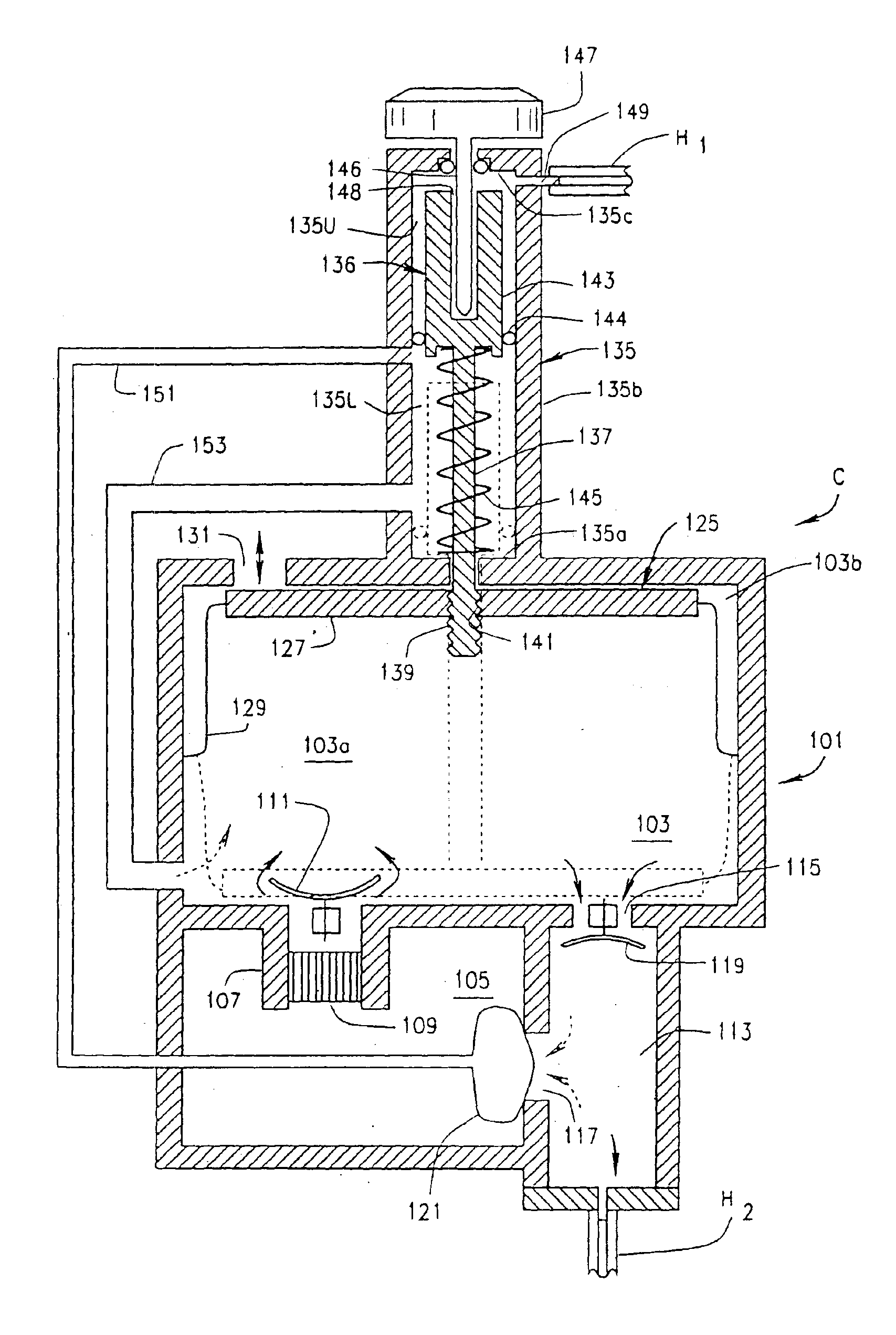
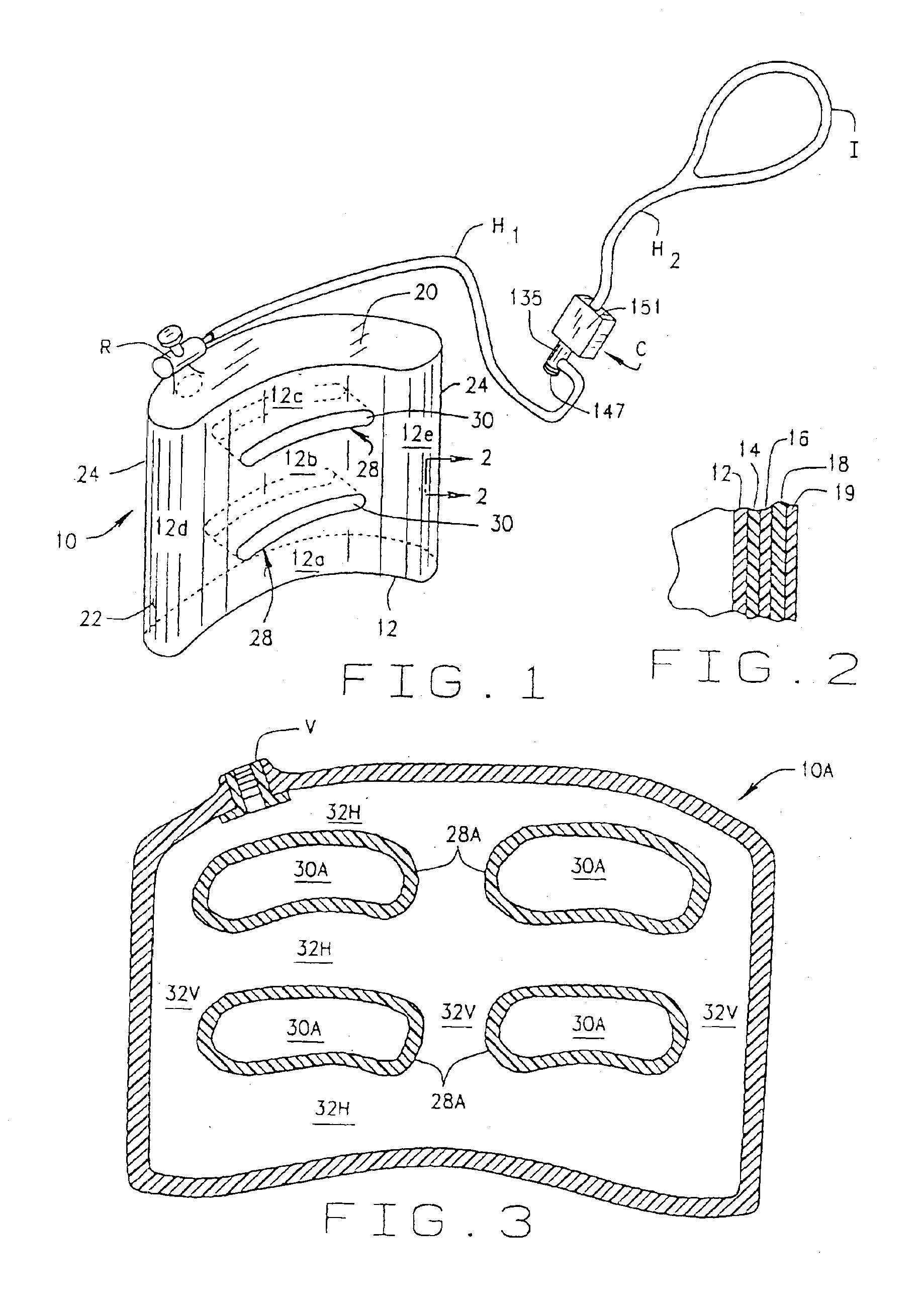
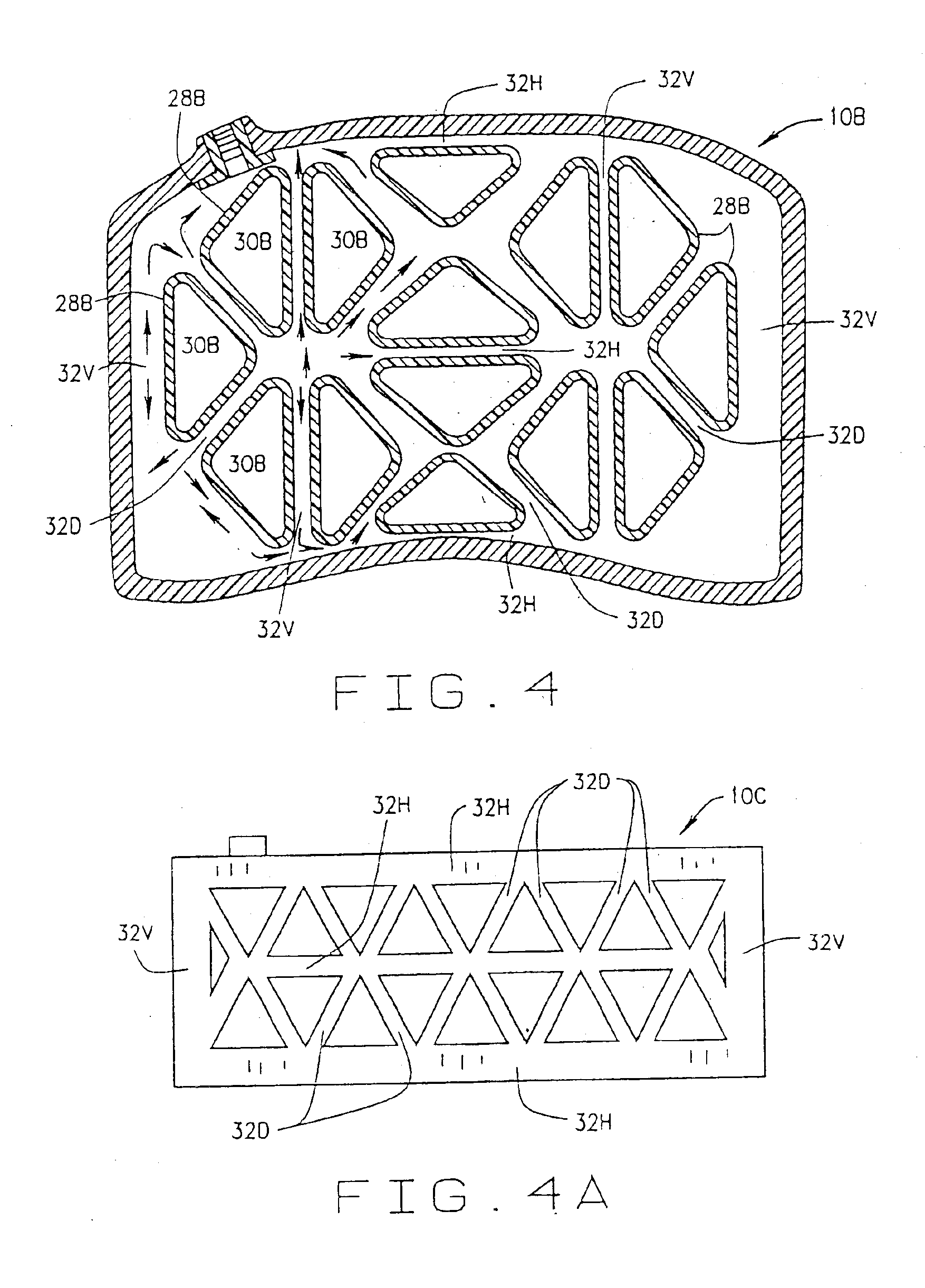
The following detailed description illustrates the invention by way of example and not by way of limitation. This description will clearly enable one skilled in the art to make and use the invention, and describes several embodiments, adaptations, variations, alternatives and uses of the invention, including what I presently believe is the best mode of carrying out the invention. Although my system is described primarily in conjunction for use with therapeutic gases (i.e., oxygen), it will be appreciated that the container can be used with any other gas or gas mixtures which is pressurized. Thus, for example, the container also can be used to store hydrogen, helium, nitrogen, acetylene, etc. This list, of course, is exemplary only, it is not intended to be limiting, and it will be understood that other gases or gas mixtures can also be stored in the container of the present invention.

The feasibility of using a polymeric container for medical, emergency or recreational gases has neve...


PUM

PropertyMeasurementUnit
pressureaaaaaaaaaa
pressuresaaaaaaaaaa
length of timeaaaaaaaaaa

Abstract

A pressurized gas supply system includes a pressurized container which expands and contracts. The container includes a one-piece liner molded from a polymer which is reinforced by a high tensile fiber such as KEVLAR®. A valve is molded into the liner, and a regulator is connected to the valve. A hose, having a conserver positioned therealong, extends between the regulator and a fitting allowing a user to inhale gas from the container. The container is carried in a carrying bag, which can be in the form of a carrying case, a purse, or a back-pack.

Description

STATEMENT REGARDING FEDERALLY SPONSORED RESEARCH OR DEVELOPMENTNot Applicable.BACKGROUND OF THE INVENTIONThis invention relates to storage systems for pressurized gasses, and, in particular, to an expandable, collapsible ambulatory storage system.High-pressure gases are typically stored in steel or aluminum containers. For example, oxygen is stored in steel or aluminum containers (or cylinders) for use in aviation (spacecrafts, private, military and commercial airplanes), by scuba divers, in hospitals, emergency vehicles, and by patients requiring oxygen therapy. In aviation, oxygen is supplied in specially designed high-pressure canisters.In the medical field supplemental oxygen is prescribed to patients who suffer from a variety of respiratory disorders, due to respiratory insufficiency or respiratory failures such as, obstructive pulmonary disease, chronic bronchitis, interstitial or restrictive lung disease, emphysema, congestive heart failure and during surgical operations. The...

Claims


Application Information

Patent Timeline
Patent Type & Authority Patents(United States)
IPC IPC(8): A61M16/00F17C1/06F17C1/16F17C1/00F17C1/02A61M16/06
CPCA61M16/0677A61M16/00F17C1/02F17C1/06F17C1/16F17C2201/0147F17C2201/0195F17C2201/058F17C2203/013F17C2203/0604F17C2203/0607F17C2203/0619F17C2203/0621F17C2203/0624F17C2203/066F17C2203/0665F17C2203/0673F17C2203/0685F17C2205/0115F17C2205/0126F17C2205/0165F17C2205/0323F17C2205/0338F17C2205/0364F17C2205/0394F17C2209/2118F17C2209/2127F17C2209/2145F17C2209/225F17C2209/227F17C2209/232F17C2221/011F17C2221/012F17C2221/014F17C2221/017F17C2221/018F17C2221/03F17C2223/0123F17C2223/036F17C2225/0123F17C2225/033F17C2250/03F17C2250/0426F17C2250/043F17C2250/0452F17C2250/0495F17C2250/0626F17C2250/0636F17C2250/0642F17C2260/011F17C2260/012F17C2270/0189F17C2270/0194F17C2270/025F17C2270/07F17C2270/0781F17C2270/079Y02E60/321A61M2202/03A61M2205/50A61M2230/432A61M2230/435F17C2201/0128F17C2201/0176A61M16/22A61M2202/0208A61M16/024Y02E60/32A61M2202/0007
Inventor IZUCHUKWU, JOHN I.
Owner IZUCHUKWU JOHN I
Why Eureka
Try Eureka