Temperature-controlled chuck with recovery of circulating temperature control fluid

a temperature control and chuck technology, applied in the field of temperature control systems, can solve problems such as substantial fluid loss, and achieve the effect of eliminating substantial fluid loss

Inactive Publication Date: 2005-03-15
TEMPTRONIC
View PDF34 Cites 28 Cited by
  • Summary
  • Abstract
  • Description
  • Claims
  • Application Information

AI Technical Summary

Benefits of technology

[0014]The system and method of the invention provides numerous advantages over prior approaches to temperature control using circulated fluids. Because the residual fluid can be purged from the chuck of the invention, the drawbacks associated with fluorine ions breaking out of the fluid at high temperatures are substantially eliminated. Also, by condensing the fluid vapor and returning it to the temperature control system, substantial fluid loss is eliminated. These advantages provided by the invention make the environmentally friendly hydrofluoroether class of fluids applicable to high-temperature semiconductor wafer fabrication and testing.

Problems solved by technology

Were these vapors to be simply vented to the atmosphere, substantial fluid loss would result.

Method used


Image

  • Temperature-controlled chuck with recovery of circulating temperature control fluid
  • Temperature-controlled chuck with recovery of circulating temperature control fluid
  • Temperature-controlled chuck with recovery of circulating temperature control fluid

Examples


Embodiment Construction

of the evaporator of FIG. 3 in accordance with the invention.

[0020]FIGS. 5A and 5B contain schematic cross-sectional views of one embodiment of the distribution manifold in accordance with the invention.

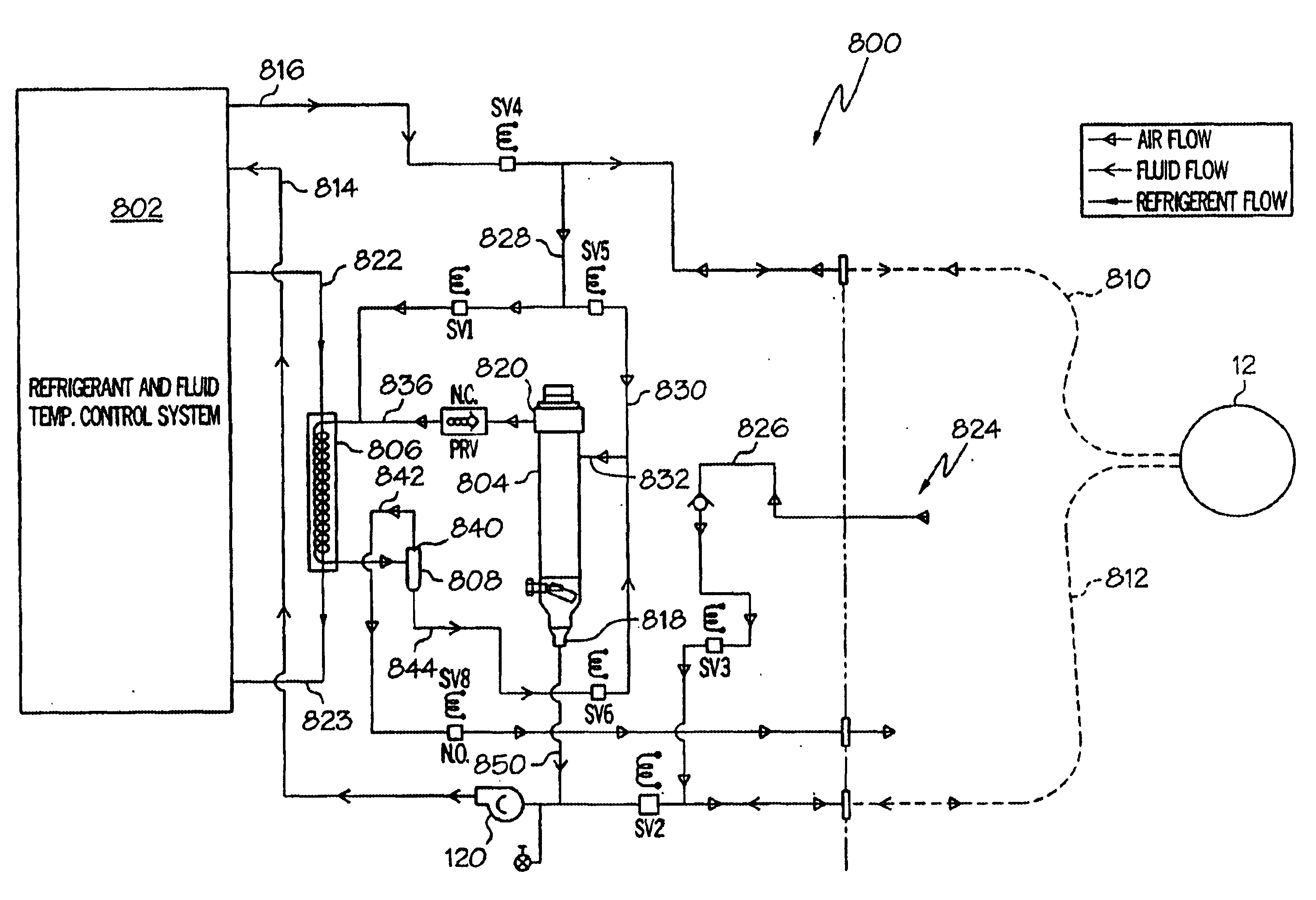
[0021]FIG. 6 is a schematic functional block diagram of a chuck temperature control system in which circulating temperature control fluid is purged from the chuck and circulation lines and is returned to the fluid circulation system.

[0022]FIG. 7A is a diagram of the fluid separator (modified accumulator), in accordance with one embodiment of the invention.

[0023]FIG. 7B is a cross-sectional view of the separator of the invention, taken along line A—A of FIG. 7A.

DETAILED DESCRIPTION OF PREFERRED EMBODIMENTS OF THE INVENTION

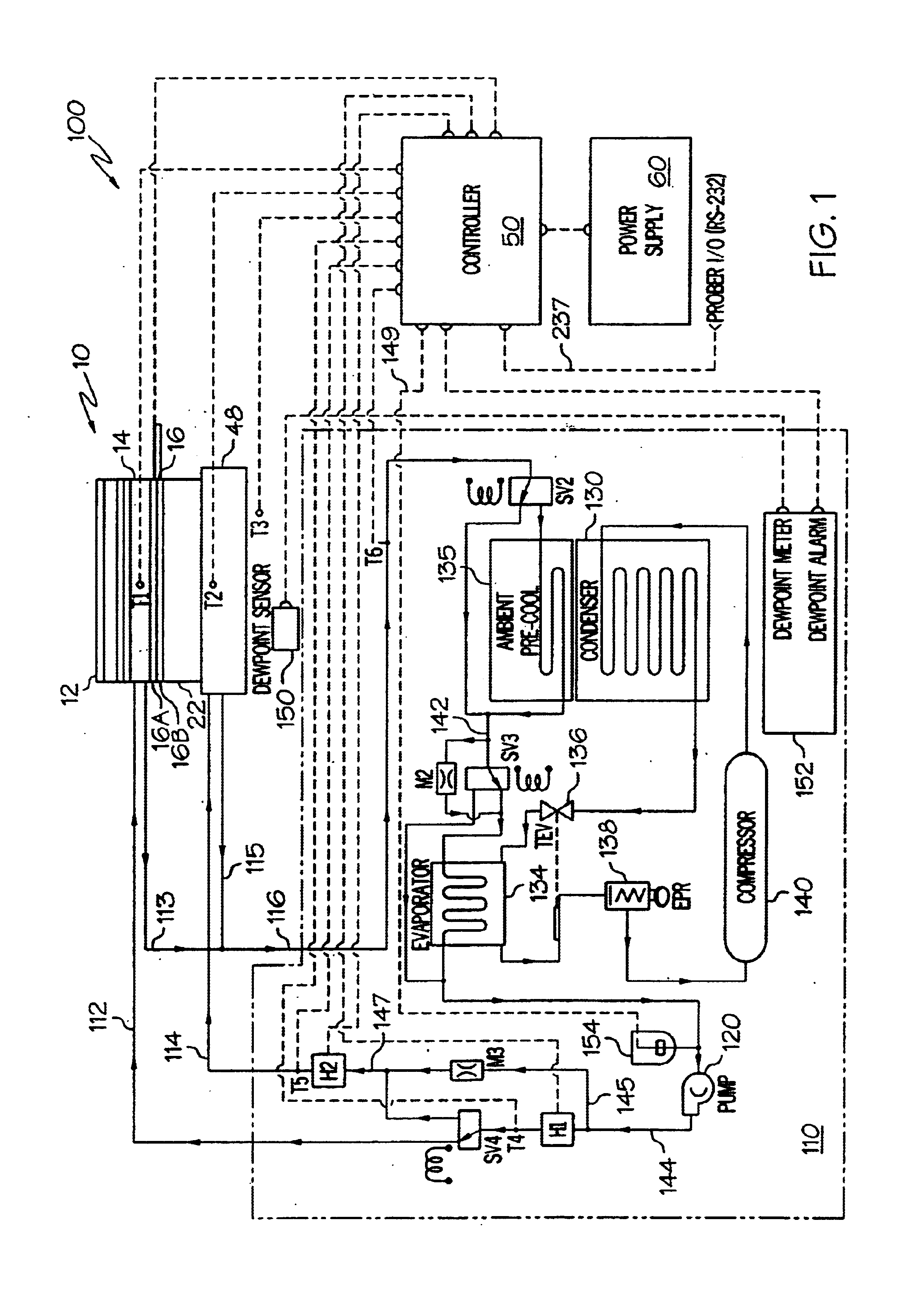
[0024]FIG. 1 is a schematic diagram of one particular temperature control system 100 in which the heat exchanger and temperature control approach in accordance with the present invention can be used. The temperature control system in the example of FIG. 1 is used in ...


PUM

PropertyMeasurementUnit
temperatureaaaaaaaaaa

Abstract

A system and method for controlling temperature in a workpiece chuck are described. A fluid circulation system circulates a temperature control fluid, such as an engineered HFE fluid, through te workpiece chuck. A fluid recovery system coupled to the fluid circulation system recovers a portion of the temperature control fluid from the fluid circulation system by circulating a gas through the fluid circulation system including fluid tubes and fluid passages in the chuck. The gas, which can be air, carries a portion of residual or excess fluid through the fluid circulation system as it is circulated. The residual fluid is carried back to a reservoir such that it can continue to be used to control temperature of the chuck. Where gas and temperature control fluid vapors are displaced from the reservoir, they are routed through a suction line heat exchanger which condenses the vapor. The gas and condensed fluid are separated in a fluid separator. The separated fluid is returned to the reservoir, and the separated air can be vented to the atmosphere.

Description

RELATED APPLICATIONS[0002]This application is a continuation-in-part of U. S. application Ser. No. 09 / 614,488, filed on Jul. 11, 2000, now issued U.S. Pat. No. 6,505,478, issued on Jan. 14. 2003, the contents of which are incorporated herein in their entirety by reference.FIELD OF THE INVENTION[0003]The present invention relates generally to temperature control systems and more specifically to temperature control systems used to control the temperature of a workpiece such as a semiconductor wafer and / or to control the temperature of the workpiece chuck on which the workpiece is held.BACKGROUND OF THE INVENTION[0004]In the semiconductor integrated circuit industry, the cost of individual integrated circuit chip die is continuing to decrease in comparison to IC package costs. Consequently, it is becoming more important to perform many IC process steps while the die are still in the wafer, rather than after the relatively expensive packaging steps have been performed.[0005]Typically, i...

Claims


Application Information

Patent Timeline
Patent Type & Authority Patents(United States)
IPC IPC(8): B23Q11/14B23Q11/12F28F27/00F28F27/02F25B41/04F25B39/02G01R31/28H01L21/00H01L21/687H01L21/67F25B9/00F25B41/00F25D17/02F28F9/22H01L21/02H01L21/66H01L21/683
CPCB23Q11/126H01L21/687B23Q11/141B23Q11/143F25B39/028F25B41/04F28F9/028F28F27/00G01R31/2865G01R31/2874G01R31/2891H01L21/67103H01L21/67248B23Q11/127F25B9/002F28D2021/0077G01R31/2831F25B41/20F25B41/24
Inventor COUSINEAU, SHAWN M.KELSO, ROBERT D.OLSEN, DOUGLAS S.STURA, DAVID
Owner TEMPTRONIC
Why Eureka
Try Eureka