
Chisel holder changing system with chisel holder receivers

a technology of chisel holder and receiver, which is applied in the direction of screws, threaded fasteners, manufacturing tools, etc., can solve the problems of difficult or even impossible release of screw connection, extensive repair work, etc., and achieve the effect of simple screw connection

Inactive Publication Date: 2005-03-15
WIRTGEN GMBH
View PDF6 Cites 64 Cited by
  • Summary
  • Abstract
  • Description
  • Claims
  • Application Information

AI Technical Summary

Benefits of technology

This patent is about a system for easily changing chisel holders on a chisel holder changing system. The system uses a bracing screw and a threaded receiver to secure the chisel holder. The invention provides a simple screw connection between the bracing screw and the threaded receiver that can withstand large prestressing forces without damaging the connection. The connection is protected against corrosion by a metallic layer of zinc and aluminum lamellas and a mineral chromium oxide bonding agent. The layer is applied by dipping, centrifuging, or spraying and is burned in at approximately 300°C. The coating is non-electrolytic and does not require rinsing. The metallic layer is formed by a chemical reaction between the layer material and the metal base during the burning-in process. The shoulder of the bracing screw is designed to reduce the risk of damage to the threaded connection and facilitate easy disassembling without damage to the screw threads. The bracing screw can be designed as a stud screw and is completely removed from the closing area.

Problems solved by technology

If they are too great, the tool receivers of the bracing screws can become damaged, so that the release of the screw connection is difficult or even impossible.
This then results in extensive repair work.

Method used


Image

  • Chisel holder changing system with chisel holder receivers
  • Chisel holder changing system with chisel holder receivers

Examples


Embodiment Construction

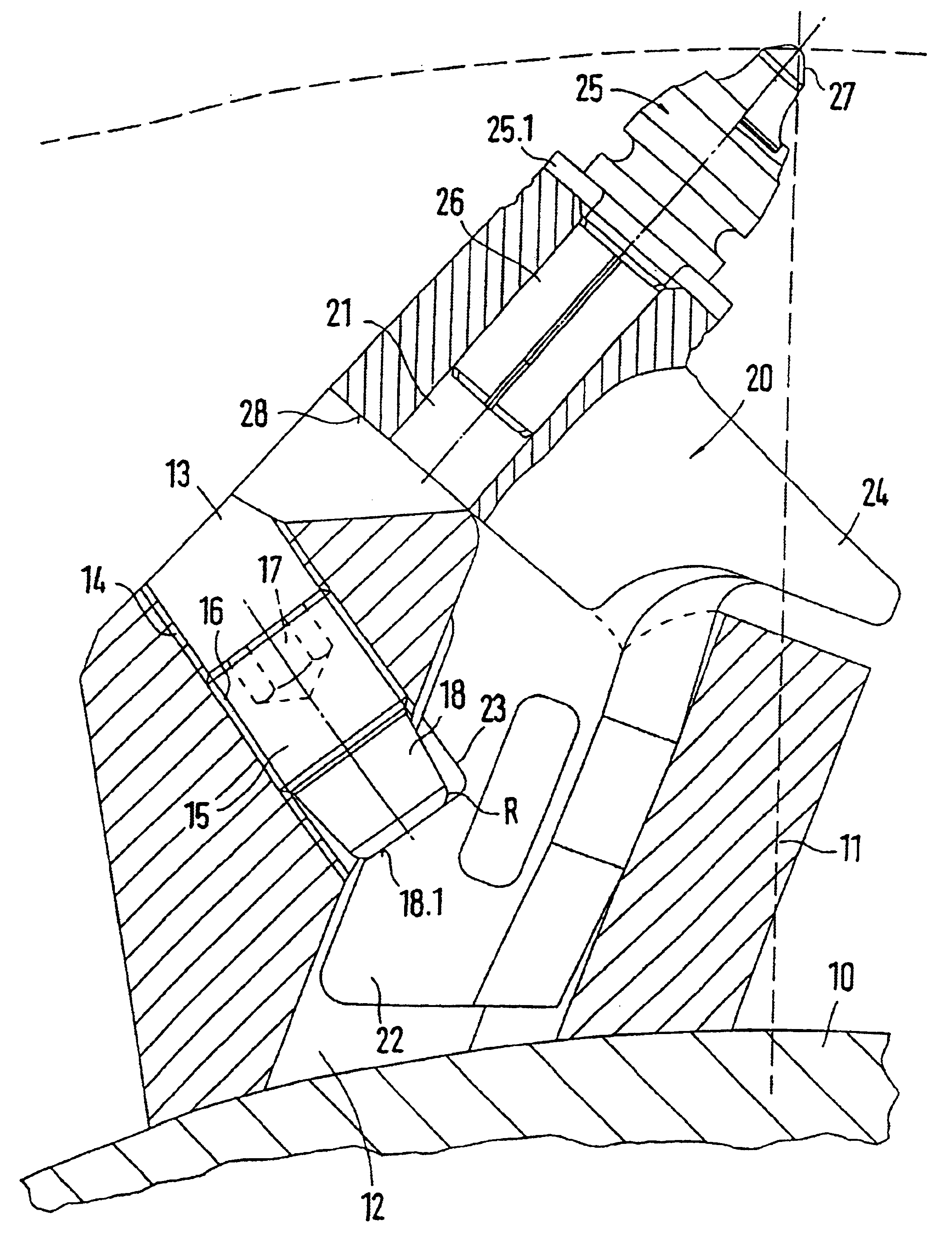
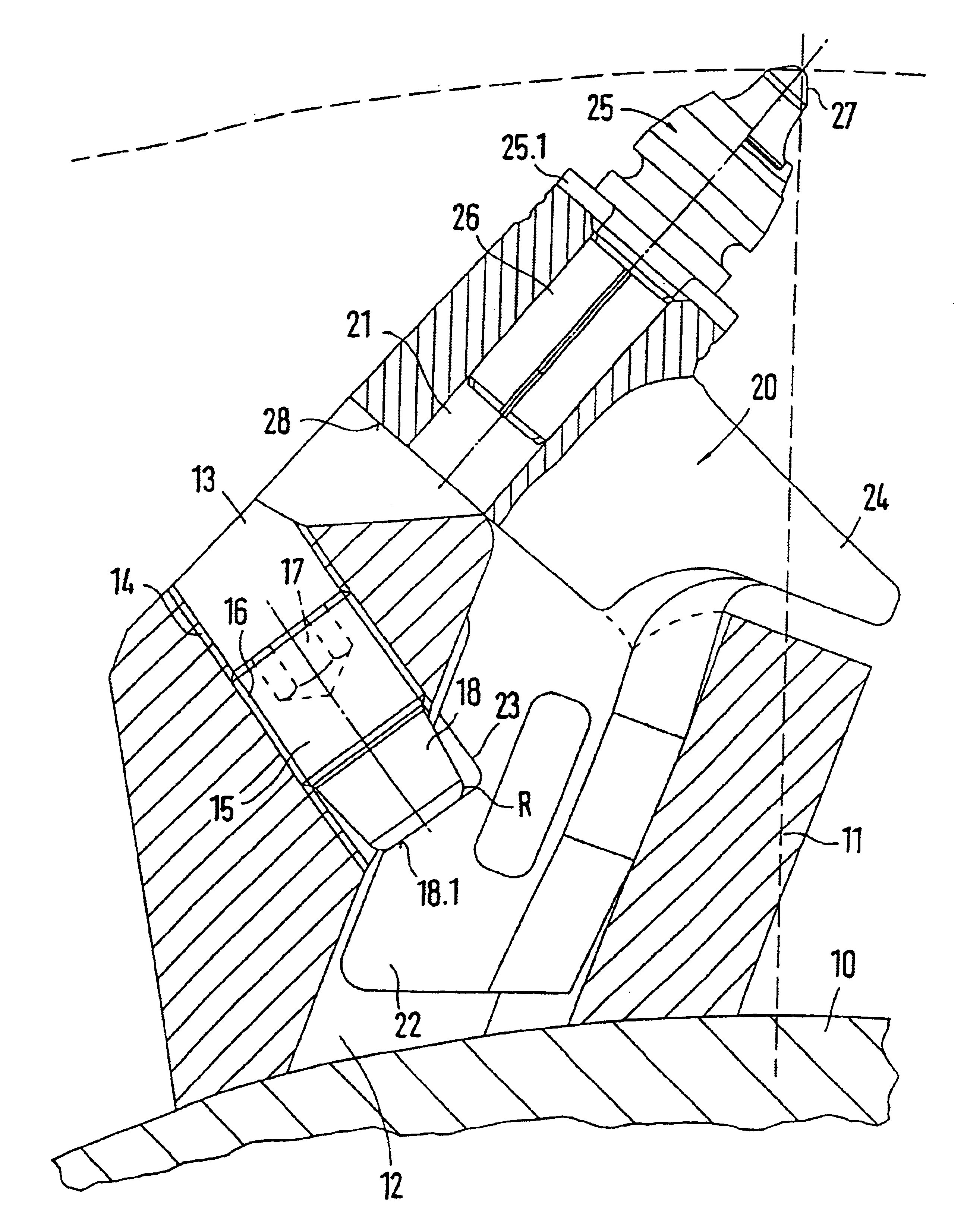
The chisel holder changing system of this invention comprises a base element 11 and a chisel holder 20. The base element 11 is fastened on the surface of a milling roller 10, preferably welded on it. The base element 11 has a chisel holder receiver 12. The chisel holder 20 is inserted into the chisel holder receiver 12 with a holder shaft 22. The holder shaft 22 has a cut in a bracing receiver 23. The bracing receiver 23 is accessible via a threaded receiver 13. The threaded receiver 13 is cut into the base element 11. A bracing screw 15 is used for fixing the chisel holder 20 in place on the base element 11. The bracing screw 15 is designed as a stud screw and has a tool receiver 17 (hexagon socket) in its head. The bracing screw 15 is screwed into the inner screw thread 14 of the threaded receiver 13 with its outer screw thread 16. The bracing screw 15 has a shoulder 18 on its end facing away from the tool receiver 17. The shoulder 18 is embodied as a truncated cone and continuous...


PUM


Abstract

A chisel holder changing system having a base element with a chisel holder receiver, into which a chisel holder equipped with a chisel can be inserted, wherein the chisel holder is inserted with a holder shaft into the chisel holder receivers and is maintained therein with the aid of bracing screws. Bracing screws can be screwed into a threaded receiver of the base element and during this are supported under tension in a bracing receiver of the holder shaft of the chisel holder. If in a chisel holder changing system in accordance with this invention the surfaces of the outer screw thread of the bracing screw and / or of the inner screw thread of the threaded receivers of the chisel holder receivers have a metallic layer of zinc and aluminum lamellas and a mineral chromium oxide bonding agent, which is burned in after the application, the screw connections are improved so that larger prestressing forces / tightening torques can be transmitted without damage to the screw connections.

Description

BACKGROUND OF THE INVENTION1. Field of the InventionThis invention relates to a chisel holder changing system having a base element with a chisel holder receiver, into which a chisel holder equipped with a chisel can be inserted, wherein the chisel holder is inserted with a holder shaft into the chisel holder receivers and is maintained therein with bracing screws. The bracing screws can be screwed into a threaded receiver of the base element and during this are supported under tension in a bracing receiver of the holder shaft of the chisel holder.2. Discussion of Related ArtChisel holder changing systems are used with milling rollers of milling machines, for example road milling machines. The chisels in the chisel holders, as well as the chisel holders in the chisel holder receivers, can be changed, so that they can be replaced in case of wear, damage, and the like, without removing the chisel holder changing system from the milling machine.For a definite seating of the chisel hold...

Claims


Application Information

Patent Timeline
Patent Type & Authority Patents(United States)
IPC IPC(8): E21C35/193E21C35/00E21C35/18E21C35/19
CPCE21C35/193E21C2035/1826Y10S411/903Y10S411/914E21C2035/191E21C35/191E21C35/188
Inventor HOLL, BERNDHAHN, GUNTER
Owner WIRTGEN GMBH
Learn More