
Non-contact type rotation-angle sensing device

a sensing device and non-contact technology, applied in the direction of measuring devices, magnetic measurements, instruments, etc., can solve the problems of increasing cost, difficult to stabilize the density of magnetic flux, and inability to secure linearity, so as to remove the magnetic hysteresis of the sensor output and reduce the cost

Inactive Publication Date: 2005-03-15
MITSUBISHI ELECTRIC CORP
View PDF8 Cites 16 Cited by
  • Summary
  • Abstract
  • Description
  • Claims
  • Application Information

AI Technical Summary

Benefits of technology

The present invention was made to solve the above-discussed problems and has an object of obtaining a non-contact type rotation-angle sensing device in which a simple magnetic circuit is arranged employing a permanent magnet and a rotation angle sensor having magnetoresistance elements (MR elements). This non-contact type rotation-angle sensing device secures linearity by removing magnetic hysteresis of the sensor output with respect to rotation angle and achieves small-sized permanent magnet and reduction in cost.
In the non-contact type rotation-angle sensing device of above constitution according to the invention, linearity is secured by reducing magnetic hysteresis of the sensor output with respect to the rotation angle, and a small-sized permanent magnet and reduction in cost are achieved.

Problems solved by technology

However, in order to judge the switching and detect the rotation angle, plural rotation angle sensors are required, which results in a problem of increase in cost.
It is, however, difficult to stabilize density of magnetic flux passing through the rotation angle sensor through the soft magnetic material when the permanent magnets rotate, and it is not possible to secure linearity.
In other words, a problem exists in that the distance between the permanent magnets and the soft magnetic material has no linearity with respect to the rotation angle.
Moreover, when the rotating direction is reversed thereby reversing the magnetic flux passing through the soft magnetic material, magnetic hysteresis may cause further deterioration in linearity, which is a further problem.
However, this known device also has a problem of linearity being affected by magnetic hysteresis when the rotating direction is reversed thereby reversing the direction of the passing magnetic flux.
However, the most part of the magnetic flux generated from the permanent magnet leaks outside the rotation angle sensor (the magnetoresistance element), and therefore it is essential to use a large size permanent magnet, which results in increase in cost.
The permanent magnet is expensive because it is essential to use rare earth metals (such as Sm—Co system and Nd—Fe—B system) of superior heat-resisting property and coercive force as the material of the permanent magnet.
If the rotation angle sensor output is erroneously provided, the engine control becomes unstable, whereby unstable idle rotation, poor fuel efficiency, etc. will occur.
In the worst case, there is a likelihood of engine stopping or running out of control.
In order to cope with these problems, two rotation angle sensors are used in view of fail-safe operation and, moreover, the non-contact type rotation-angle sensing device itself is undesirably large-sizes eventually resulting in increase in cost.
As a result, there remains a problem of magnetic hysteresis generated by the change in magnetic flux due to rotation.
A problem, however, exists in that it is necessary to use a large size permanent magnet to secure the linearity.

Method used


Image

  • Non-contact type rotation-angle sensing device
  • Non-contact type rotation-angle sensing device
  • Non-contact type rotation-angle sensing device

Examples


embodiment 1

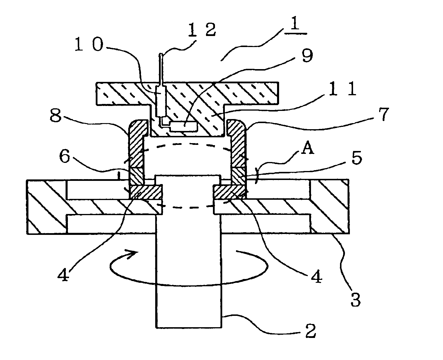
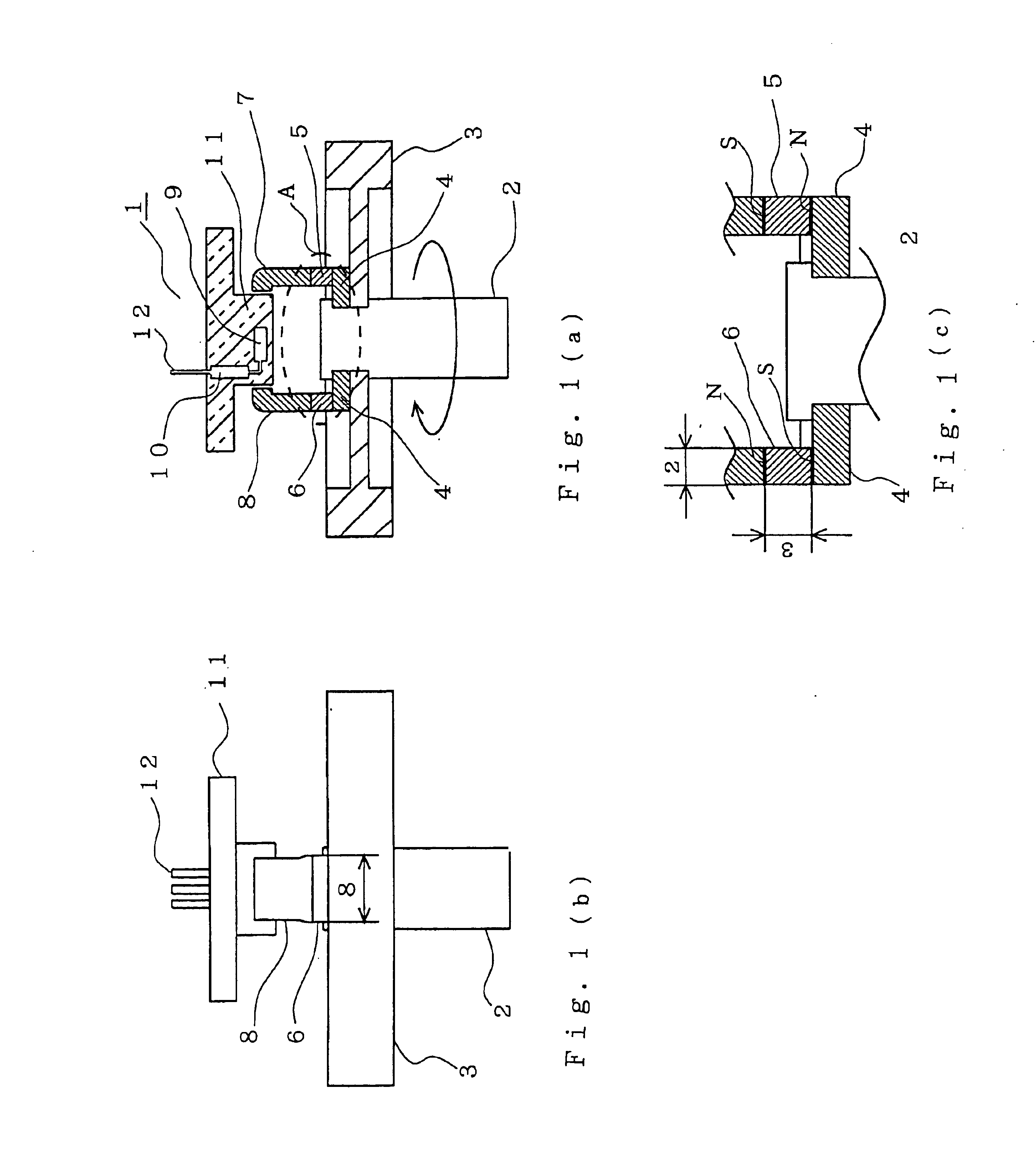
Now reference is made to FIG. 1(a) showing a sectional view, FIG. 1(b) showing a side view, and FIG. 1(c) showing an enlarged view of an essential part of the sectional view in FIG. 1(a). In these drawings, a non-contact type rotation-angle sensing device 1 has a rotatable disk 3 (made of a non-magnetic material such as stainless steel) fixed to a rotary shaft 2 (made of a non-magnetic material such as stainless steel). Doughnut-shaped magnetic elements 4, 4 (made of iron such as steel plate) are respectively fixed onto the rotatable disk 3 symmetrically about the rotary shaft 2. Permanent magnets 5 and 6 are respectively fixed onto the two magnetic elements 4 symmetrically about the rotary shaft 2. Strip magnetic elements 7 and 8 (made of iron such as steel plate) are respectively fixed onto the two permanent magnets 5 and 6 symmetrically about the rotary shaft 2. A rotation angle sensor 9 having magnetoresistance elements (MR elements) perpendicular to an extension line of the rot...

embodiment 2

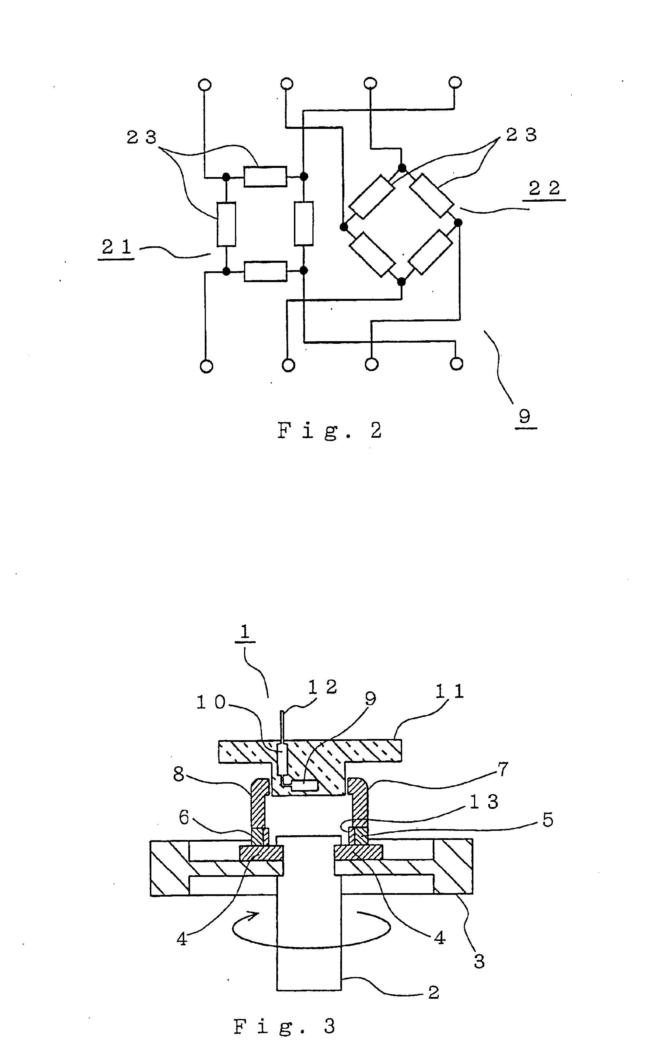
FIG. 3 is a sectional view showing a non-contact type rotation-angle sensing device according to Embodiment 2 of the invention. In the magnetic circuit, magnetic flux flowing from the N-pole to S-pole between the same permanent magnet is generated on a plane parallel to the polarizing direction of the permanent magnets 5 and 6. There is a possibility that the leakage flux therefrom interferes with the space around the rotation angle sensor 9 (magnetoresistance elements). In order to avoid this interference, it is necessary to dispose the rotation angle sensor 9 (magnetoresistance elements) at a distance (calculated specifically by a finite element method, for example) where the rotation angle sensor 9 is free from the influence of the permanent magnets 5 and 6. For that purpose, it is possible to prevent the leakage flux and shorten the distance by disposing a plate-like magnetic element 13 on the face where the leakage takes place.

The plate-like magnetic element 13 (made of iron su...

embodiment 3

FIGS. 4(a) and (b) show respectively a non-contact type rotation-angle sensing device according to Embodiment 3 of the invention, and in which FIG. 4(a) is a sectional view and FIG. 4(b) is a view showing a constitution of an essential part. An annular magnetic element 14 (made of iron such as steel plate) is disposed on the rotation angle sensor 9 (magnetoresistance elements) side of the permanent magnets 5 and 6. The annular magnetic element 14 is partially provided with a notch 15 in order to prevent magnetic flux getting in. Disposing the annular magnetic element 14 makes it possible to control the space and improve assembling efficiency. The annular magnetic element 14 also provides the advantages of the magnetic element 13 in the foregoing Embodiment 2 (i.e., prevention of interference of magnetic flux).


PUM


Abstract

In a non-contact type rotation-angle sensing device, a rotation angle sensor (9) having magnetoresistance elements detects a rotation angle of an object to be measured. The object is rotatable round a rotary shaft (2) with respect to the rotation angle sensor (9) and includes a permanent magnet (5, 6). The permanent magnet (5, 6) is disposed symmetrically about said rotary shaft (2) of said object, and a magnetic element (7, 8) is disposed on said object between said permanent magnet (5, 6) and the magnetoresistance elements. In the non-contact type rotation-angle sensing device of above constitution according to the invention, linearity is secured by reducing magnetic hysteresis of the sensor output with respect to the rotation angle, thus a small-sized permanent magnet and reduction in cost being achieved.

Description

BACKGROUND OF THE INVENTION1. Field of the InventionThe present invention relates to a non-contact type rotation-angle sensing device that detects a rotation angle of a rotating object to be measured with the use of a permanent magnet and a rotation angle sensor having a magnetoresistance element.2. Description of the Related ArtUnder the background of improvement in durability and higher resolution in detection accuracy, it is a recent trend that rotation-angle sensing devices such as a device for detecting a throttle valve opening of an intake control system of an internal combustion engine have been changed to a non-contact type. Actually various types of non-contact type rotation-angle sensing device have been proposed. It is publicly known that a Hall element or a magnetoresistance element (MR element) is used in non-contact type rotation-angle sensing devices.In a conventional non-contact type rotation-angle sensing device disclosed in the Japanese Patent Publication (unexamin...

Claims


Application Information

Patent Timeline
IPC IPC(8): G01B7/30G01D5/245G01D5/12G01B7/00G01D5/14
CPCG01D5/147
Inventor KURITA, KAZUHISANAKAO, KENJIONISHI, YOSHIHIKOMIYAKI, MANABU
Owner MITSUBISHI ELECTRIC CORP
Learn More