Delay-locked loop (DLL) integrated circuits having high bandwidth and reliable locking characteristics

a technology of delay-locked loops and integrated circuits, applied in the direction of electrical appliances, pulse automatic control, etc., can solve the problems of increased circuit integration levels, prone to unwanted clock skew and jitter, and prone to phase error accumulation in plls, so as to reduce clock jitter characteristics and wide frequency range operation

Inactive Publication Date: 2005-03-15
INTEGRATED DEVICE TECH INC
View PDF31 Cites 121 Cited by
  • Summary
  • Abstract
  • Description
  • Claims
  • Application Information

AI Technical Summary

Problems solved by technology

However, such conventional PLL and DLL integrated circuits are frequently susceptible to unwanted clock skew and jitter as clock speed and circuit integration levels are increased.
In particular, PLLs typically suffer from phase error accumulation that may persist for long periods of time in noisy environments, whereas DLLs may have lower jitter performance because phase error accumulation does not occur.
However, DLLs typically cannot be used in applications where frequency tracking is required, such as frequency synthesis and clock recovery.
DLLs may also be difficult to design for environments that experience significant process, voltage and temperature (PVT) variations.
The operating frequency range of conventional DLLs is also frequently limited because DLLs adjust only phase and not frequency.
Unfortunately, the performance of the DLL 10 of FIG. 1 may be limited by a stuck or harmonic lock problem.
However, if TVCDL-max≧3TVCDL-min, there is no range of TCLK that meets these conditions and the DLL 10 becomes prone to the stuck problem.
Moreover, the use of a replica delay line requires the use of an additional charge pump, which can significantly increase the area and power consumption requirements of the DLL.

Method used


Image

  • Delay-locked loop (DLL) integrated circuits having high bandwidth and reliable locking characteristics
  • Delay-locked loop (DLL) integrated circuits having high bandwidth and reliable locking characteristics
  • Delay-locked loop (DLL) integrated circuits having high bandwidth and reliable locking characteristics

Examples


Embodiment Construction

The present invention now will be described more fully herein with reference to the accompanying drawings, in which preferred embodiments of the invention are shown. This invention may, however, be embodied in many different forms and should not be construed as being limited to the embodiments set forth herein; rather, these embodiments are provided so that this disclosure will be thorough and complete, and will fully convey the scope of the invention to those skilled in the art. Like reference numerals refer to like elements throughout and signal lines and signals thereon may be referred to by the same reference characters. Signals may also be synchronized and / or undergo minor boolean operations (e.g., inversion) without being considered different signals.

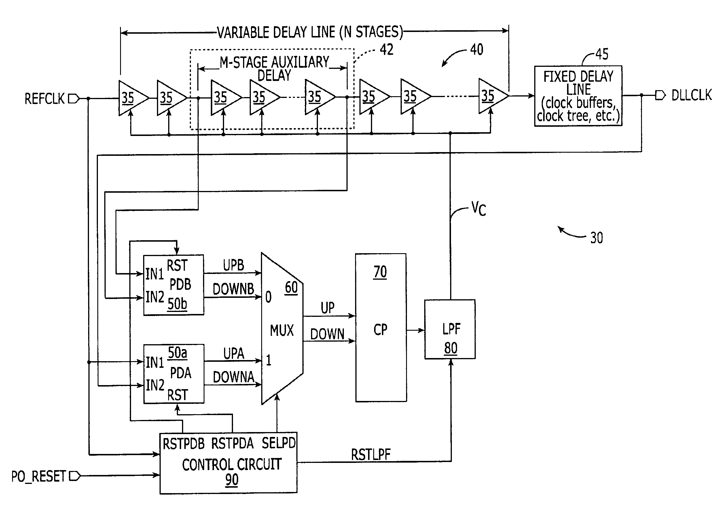
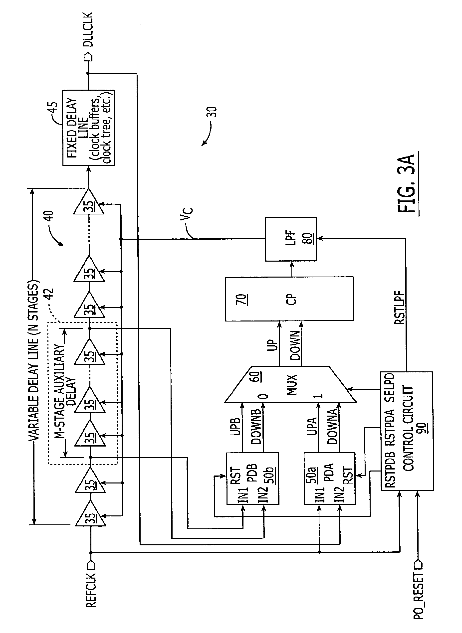
Referring now to FIG. 3A, a delay-locked loop (DLL) 30 according to an embodiment of the present invention includes a variable delay line 40 that is responsive to a reference clock signal (REFCLK). This variable delay line is illu...


PUM


Abstract

Delay-locked loops have high bandwidth locking characteristics that are less susceptible process, voltage and temperature (PVT) variations. These DLLs are configured to support transition from a partial feedback loop lock condition to a full feedback loop lock condition during a start-up time interval, in order to insure that a multi-cycle lock condition is established at the time the DLL's clock signal output becomes available. The DLL may include a variable delay line that is responsive to a reference clock signal, an auxiliary phase detector that is electrically coupled to the variable delay line, and a main phase detector that is responsive to the reference clock signal and a feedback clock signal (DLLCLK). The auxiliary phase detector may be an edge-triggered SR-type phase detector and the main phase detector may be a three-state phase frequency detector.

Description

FIELD OF THE INVENTIONThe present invention relates to integrated circuit devices and, more particularly, to integrated circuit devices having clock generators therein and methods of generating clock signals.BACKGROUND OF THE INVENTIONPhase-locked loop (PLL) and delay-locked loop (DLL) integrated circuits are frequently used to generate highly accurate internal clock signals on integrated circuit substrates (e.g., chips). However, such conventional PLL and DLL integrated circuits are frequently susceptible to unwanted clock skew and jitter as clock speed and circuit integration levels are increased. In particular, PLLs typically suffer from phase error accumulation that may persist for long periods of time in noisy environments, whereas DLLs may have lower jitter performance because phase error accumulation does not occur. Thus, DLLs may offer an important alternative to PLLs in cases where a reference clock signal comes from a low-jitter source. However, DLLs typically cannot be us...

Claims


Application Information

Patent Timeline
Patent Type & Authority Patents(United States)
IPC IPC(8): H03L7/087H03L7/081H03L7/08H03L7/089H03L7/10
CPCH03L7/0812H03L7/087H03L7/10H03L7/0891H03L7/0816
Inventor MURTAGH, PAUL
Owner INTEGRATED DEVICE TECH INC
Why Eureka
Try Eureka