Oil well acoustic logging tool with baffles forming an acoustic waveguide

a technology of acoustic waveguide and acoustic dipole signal, which is applied in the field of acoustic logging, can solve the problems of nontrivial problems and difficult measurement of acoustic dipole signal, and achieve the effect of increasing the signal to noise ratio

Inactive Publication Date: 2005-03-15
SCHLUMBERGER TECH CORP
View PDF7 Cites 11 Cited by
  • Summary
  • Abstract
  • Description
  • Claims
  • Application Information

AI Technical Summary

Benefits of technology

A second advance by Schlumberger on the DSI tool increases the signal to noise ratio in a logging tool using dipole signals by attaching regularly spaced mass blocks to the central mandrel within the spacer section and the receiver section of the dipole tool body. This causes the spacer section and the receiver section to behave acoustically like a mass-spring structure which does not interfere with the acoustic signals used for evaluation of the formation surrounding the borehole, while still providing suitable physical structure and support for the other parts of the tool. The use of regularly spaced mass blocks is disclosed in the above-mentioned co-owned, co-pending international patent application no. PCT / IB00 / 01696, filed 16 Nov. 2000, published 23 May 2002, as international publication no. WO 02 / 41034 A1.

Problems solved by technology

In certain well-bores, measurement of acoustic dipole signal can be difficult.
This problem is nontrivial because acoustic source design is constrained by the limited space within the tool body and by the limit in power supply.

Method used


Image

  • Oil well acoustic logging tool with baffles forming an acoustic waveguide
  • Oil well acoustic logging tool with baffles forming an acoustic waveguide
  • Oil well acoustic logging tool with baffles forming an acoustic waveguide

Examples


Embodiment Construction

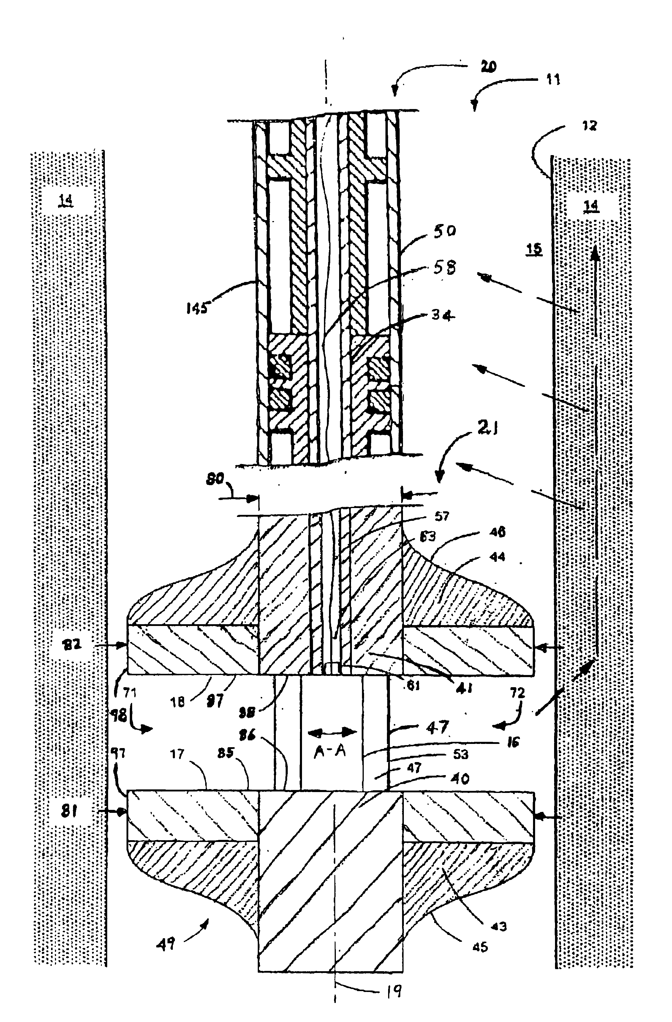
The invention provides a novel acoustic logging tool having external baffles forming a waveguide structure at the acoustic source. The waveguide structure increases the signal to noise ratio in an acoustic logging tool by increasing the received amplitude of dipole flexural mode acoustic waves. This can increase the signal to noise ratio by up to at least a factor of six. Increasing signal to noise ratio is achieved without modifying the acoustic source or increasing power to the acoustic source. This novel acoustic logging tool makes it possible to perform acoustic logging in certain well-bores in which acoustic logging is not currently possible.

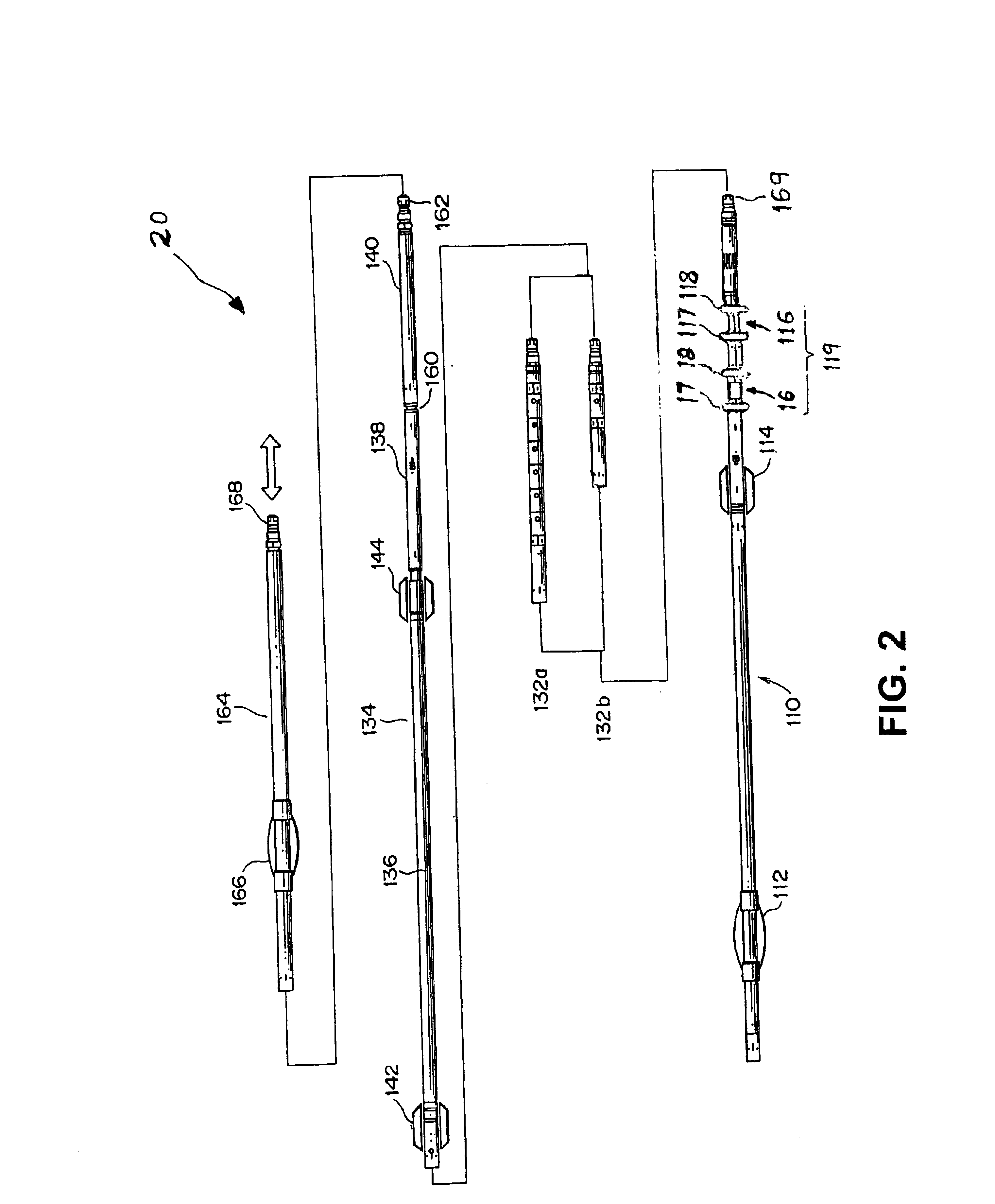
FIG. 2 is a schematic illustration of a first preferred embodiment of an acoustic logging tool 20 in accordance with the invention. Tool 20 includes an acoustic transmitter module 110 including a centralizer 112, a standoff 114, a first dipole source 16 with a lower baffle 17 and an upper baffle 18, and a second dipole source 116 with a low...


PUM


Abstract

An acoustic logging tool includes external baffle assemblies forming a waveguide structure at the acoustic source. The logging tool is designed for acoustic logging of earth formation surrounding a borehole. The external baffle assemblies form a waveguide structure that is designed to increase signal to noise ratio in an acoustic logging tool using dipole or other acoustic waves. In a preferred embodiment, the acoustic logging tool includes an elongated transmitter module, and a receiver sonde having a linear array of acoustic receivers. The transmitter module includes first and second cylindrical masses spaced apart along the axis by first and second spacers. The first cylindrical mass defines a first circular facing surface and a first cylindrical outer surface. The second cylindrical mass defines a second circular facing surface and a second cylindrical outer surface. A multi-pole acoustic source is fixedly mounted between the first and second circular facing surfaces, and located on the transmitter module axis between the first and second spacers. A first annular baffle assembly surrounding the first cylindrical outer surface has a first annular facing surface co-planar with the first circular facing surface. A second annular baffle assembly surrounding the second cylindrical outer surface has a second annular facing surface co-planar with the second circular facing surface. The annular baffle assemblies form an acoustic waveguide.

Description

FIELD OF THE INVENTIONThe invention relates to acoustic logging in oilfield geological formations. More particularly, the invention relates to apparatus and methods for increasing the signal to noise ratio in logging tools that use dipole or other acoustic signals.BACKGROUND OF THE INVENTIONThe field of sonic logging of boreholes in the oil and gas industry involves making acoustic measurements in the borehole at frequencies typically in the range 500 Hz-20 kHz. Below this range is typically considered as the seismic domain, above it the ultrasonic domain. A summary of the general techniques involved in borehole acoustic logging can be found in GEOPHYSICAL PROSPECTING USING SONICS AND ULTRASONICS, Wiley Encyclopedia of Electrical and Electronic Engineering 1999, pp, 340-365.In certain well-bores, measurement of acoustic dipole signal can be difficult. This problem is nontrivial because acoustic source design is constrained by the limited space within the tool body and by the limit i...

Claims


Application Information

Patent Timeline
Patent Type & Authority Patents(United States)
IPC IPC(8): G01V1/52G01V1/40
CPCG01V1/52G01V1/523Y10S367/911
Inventor WANG, CANYUNPABON, JAHIR
Owner SCHLUMBERGER TECH CORP
Why Eureka
Try Eureka