Method and apparatus for calibrating DC-offsets in a direct conversion receiver

a direct conversion receiver and offset technology, applied in the direction of dc level restoring means or bias distort correction, digital transmission, baseband system details, etc., can solve the problems of disadvantageous side effects of direct conversion receivers, and prone to signal interference. , to achieve the effect of advantageously reducing the size of the receiver used in wireless communication devices

Inactive Publication Date: 2005-03-15
QUALCOMM INC
View PDF9 Cites 56 Cited by
  • Summary
  • Abstract
  • Description
  • Claims
  • Application Information

AI Technical Summary

Benefits of technology

The present invention is a novel method and apparatus for calibrating DC offsets in a direct conversion receiver. The present DC offset calibration method and apparatus uses a frequency shifter means to non-intru...

Problems solved by technology

As our society becomes more mobile, wireless communication devices become increasingly small.
However, direct conversion receivers disadvantageously produce unwanted side effects.
Disadvantageously, as is well known, receivers are particularly prone to signal interference caused by DC offsets (i.e., standing voltages).
Unless these DC offsets are removed from any DC-coupled baseband signal, they will appear as interference in the received signal.
DC offsets often cause the AGC amplifiers 24, 26 to saturate, and thus produce degradation or total loss of the incoming signals.
However, in practice, this proves to be difficult to achieve.
Two difficulties are encountered when attempting to measure and calibrate DC offsets in direct conversion receivers.
First, any disturbances introduced by the process of measuring the DC offsets will change the DC offsets that are measured thereby, and will consequently not be removed by the calibration p...

Method used


Image

  • Method and apparatus for calibrating DC-offsets in a direct conversion receiver
  • Method and apparatus for calibrating DC-offsets in a direct conversion receiver
  • Method and apparatus for calibrating DC-offsets in a direct conversion receiver

Examples


Embodiment Construction

Throughout this description, the preferred embodiment and examples shown should be considered as exemplars, rather than as limitations on the present invention.

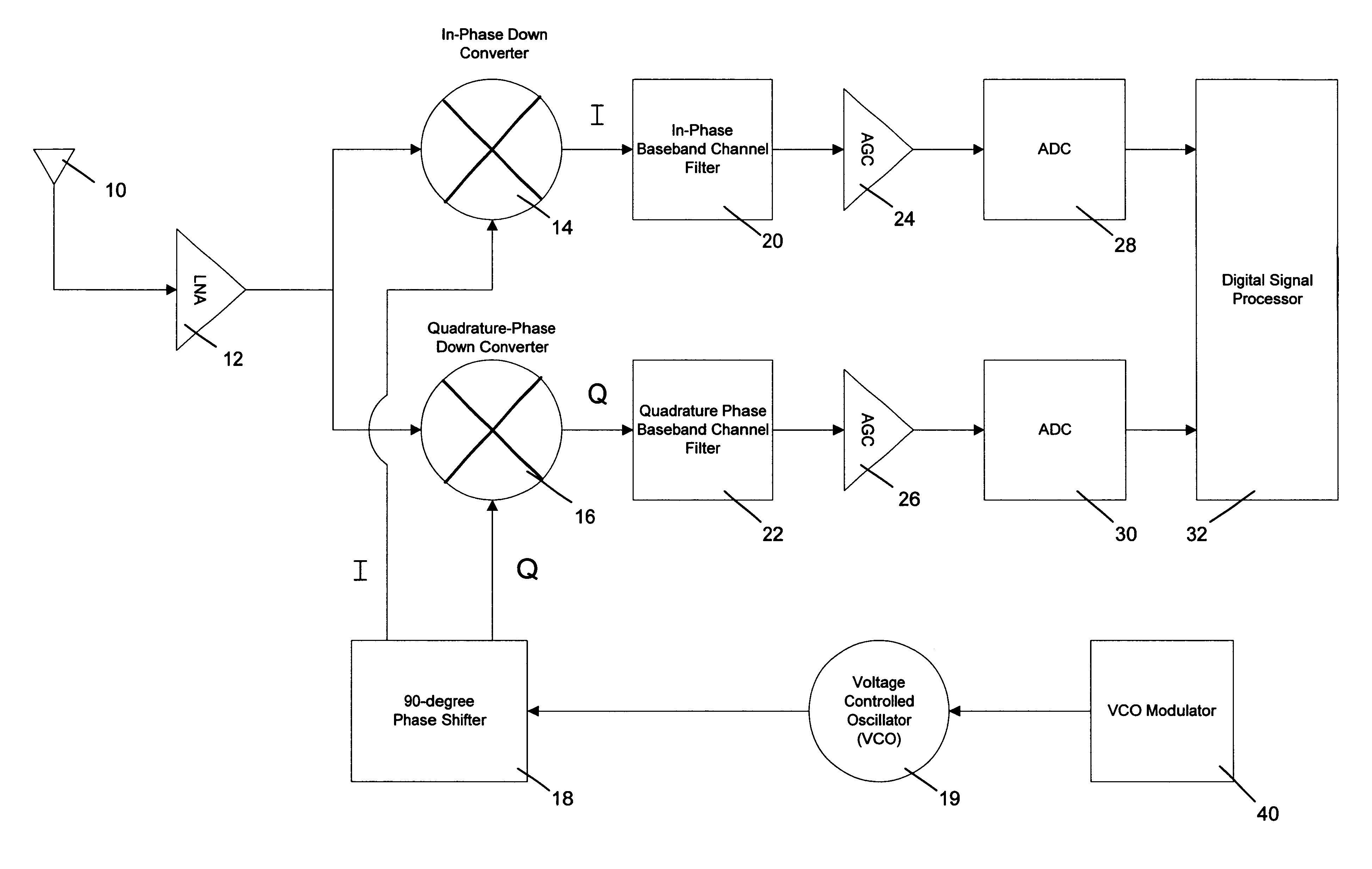
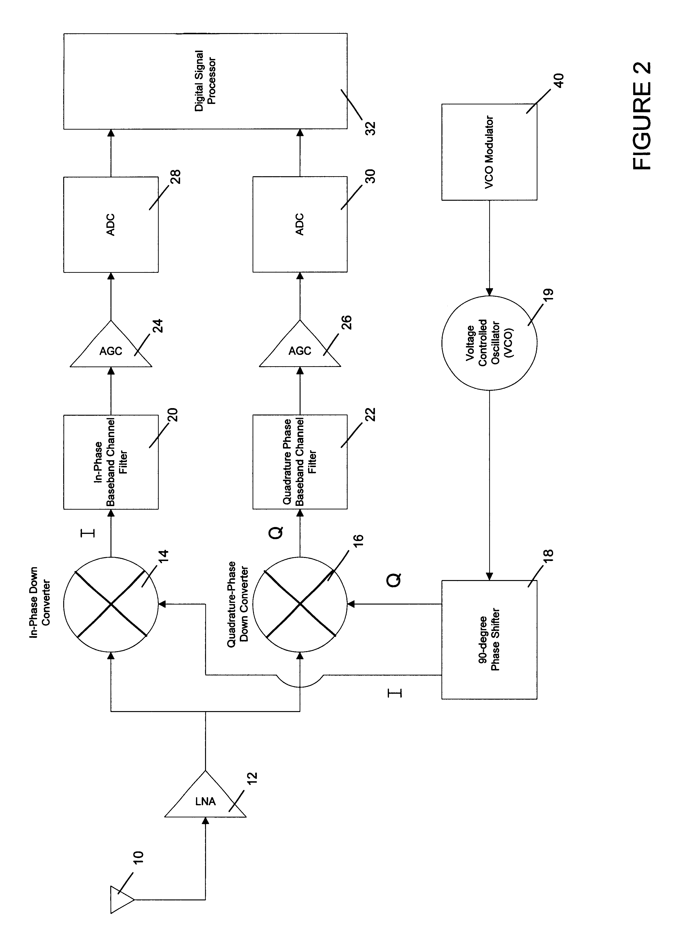
The preferred embodiment of the present invention is a method and apparatus for calibrating DC offsets in a direct conversion receiver. Direct conversion receivers facilitate reduced receiver sizes in wireless communication devices. However, as described above, these receivers produce DC offsets. DC offsets can cause a degradation or total loss of the incoming signals. Thus, it is desirable to measure and calibrate DC offsets in direct conversion receivers.

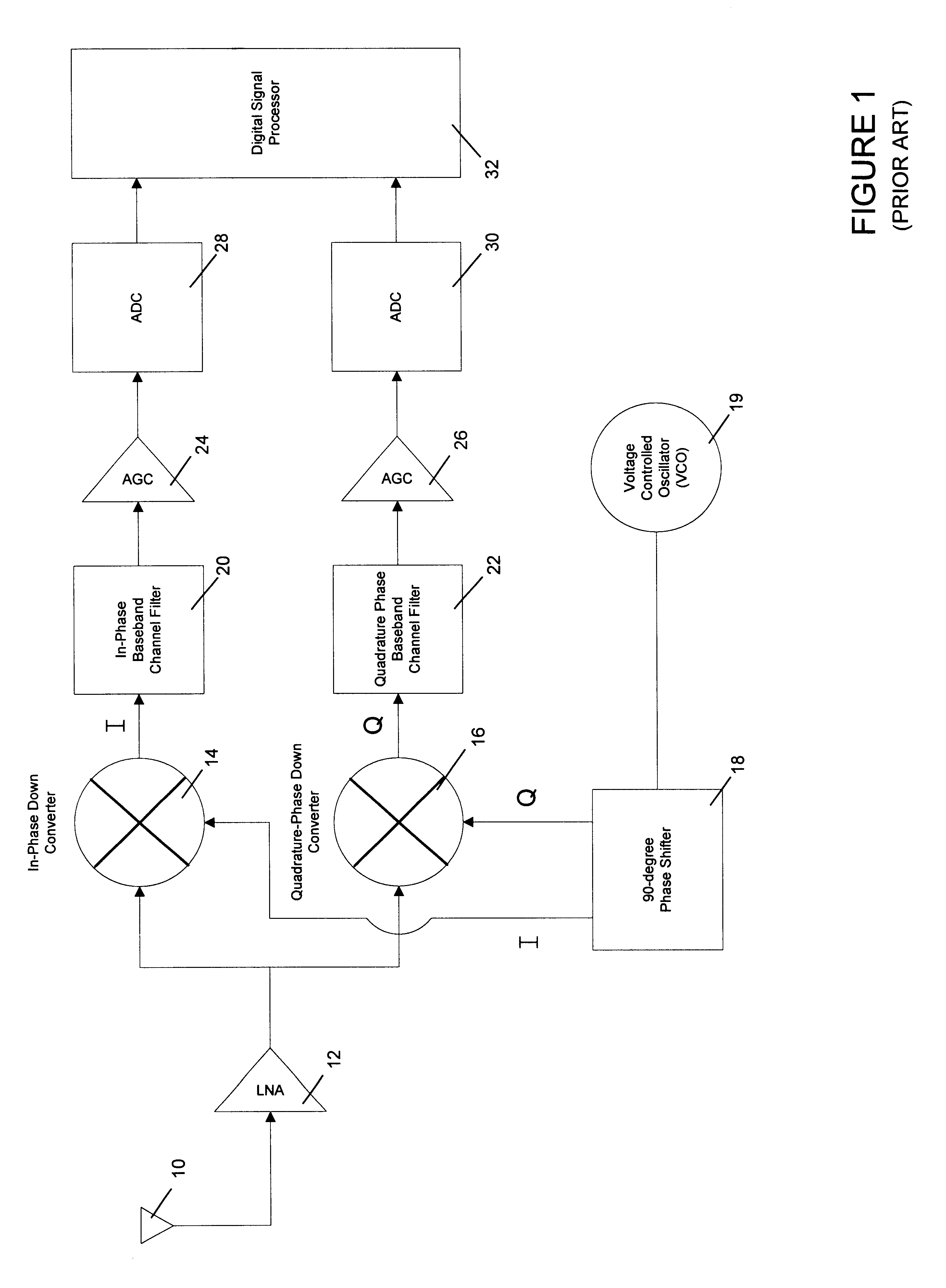
Referring again to FIG. 1, and as described above, direct conversion receivers split incoming signals, into In-Phase (I) and Quadrature Phase (Q) channel signals. The split I and Q channel signals follow two different signal-processing paths. As shown in FIG. 1, a first signal-processing path (the I-channel signal-processing path) includes the I down converter 14, the I-cha...


PUM


Abstract

A novel method and apparatus for calibrating DC offsets in a direct conversion receiver. The present DC offset calibration method and apparatus comprises a direct conversion receiver equipped with a frequency shifter means and a DC offset measurement and correction technique. In accordance with the present invention, DC offsets are calibrated in direct conversion receivers through an inventive method including two steps: a DC offset measurement step and a DC offset correction step. In the DC offset measurement step the frequency of a local oscillation signal (typically generated by a voltage-controlled oscillator (VCO)) is shifted by a selected frequency shift value during the inactive time intervals of the receiver. DC offsets are measured while the frequency of the down-conversion oscillation signal is shifted by the frequency shift value. Before the inactive time interval expires, the frequency of the down-conversion oscillator signal is shifted back to its original value. In the DC offset correction step of the present invention incoming signals are corrected using a correction means that removes the DC offset measured during the DC offset measurement step.

Description

BACKGROUND OF THE INVENTION1. Field of the InventionThis invention relates to direct conversion receivers, and more particularly to a method and apparatus for calibrating DC offsets in a direct conversion receiver.2. Description of Related ArtAs our society becomes more mobile, wireless communication devices become increasingly small. Reducing component size within portable wireless communication devices such as cellular phones, pagers and wireless personal digital assistants (PDAs) is increasingly desirable. Reducing radio receiver size provides a significant reduction in wireless communication device size. One exemplary radio receiver is a “direct conversion” receiver. Direct conversion receivers are also known as “zero intermediate frequency” (zero IF) receivers. Direct conversion receivers are well known in the wireless communication art. Direct conversion receivers are described in many prior art publications such as U.S. Pat. No. 4,944,025, issued on Jul. 24, 1990 to Gehring e...

Claims


Application Information

Patent Timeline
IPC IPC(8): H04L25/06H04L27/00H03D3/00H04B1/30
CPCH03D3/008H04B1/30H04L27/0014H04L2027/0046H04L2027/0028
Inventor LANE, MARK V.
Owner QUALCOMM INC
Why Eureka
Try Eureka