

Control method of EGR system of engine
- Summary
- Abstract
- Description
- Claims
- Application Information
AI Technical Summary
Benefits of technology
Problems solved by technology
Method used
Image

Examples
Embodiment Construction
An embodiment of a control method of an EGR system of an engine according to the present invention will be described in detail below with reference to the drawings.
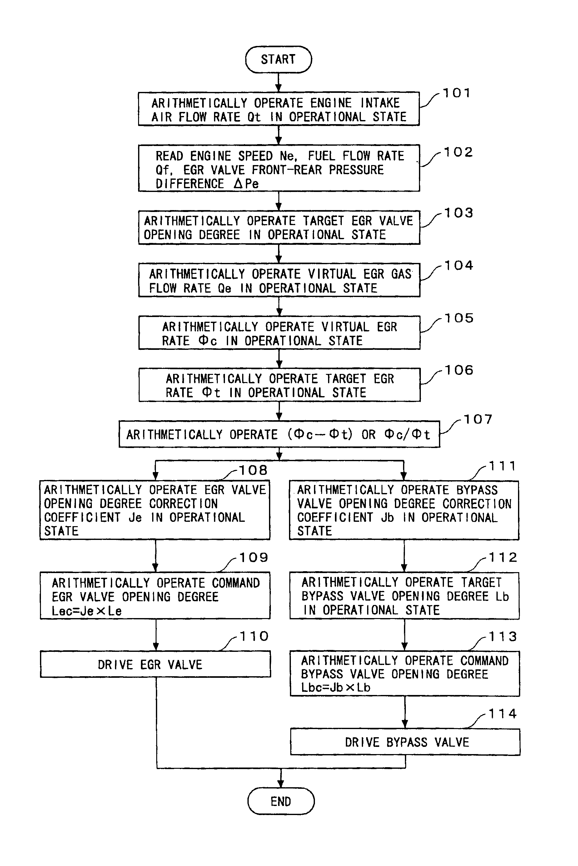
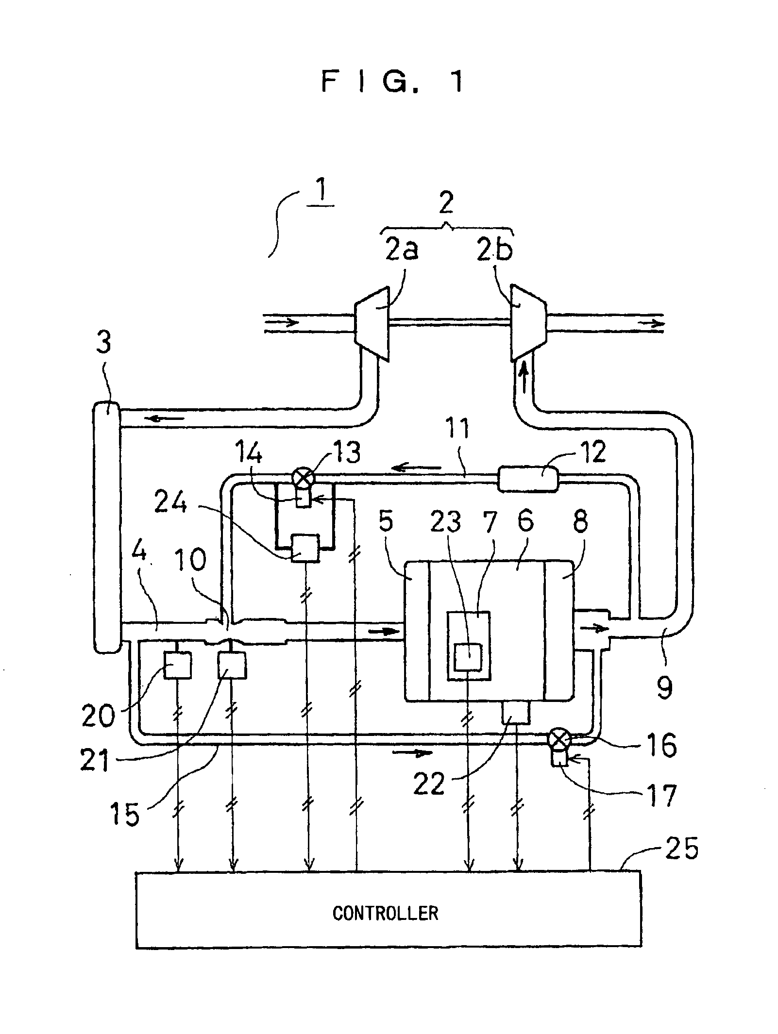
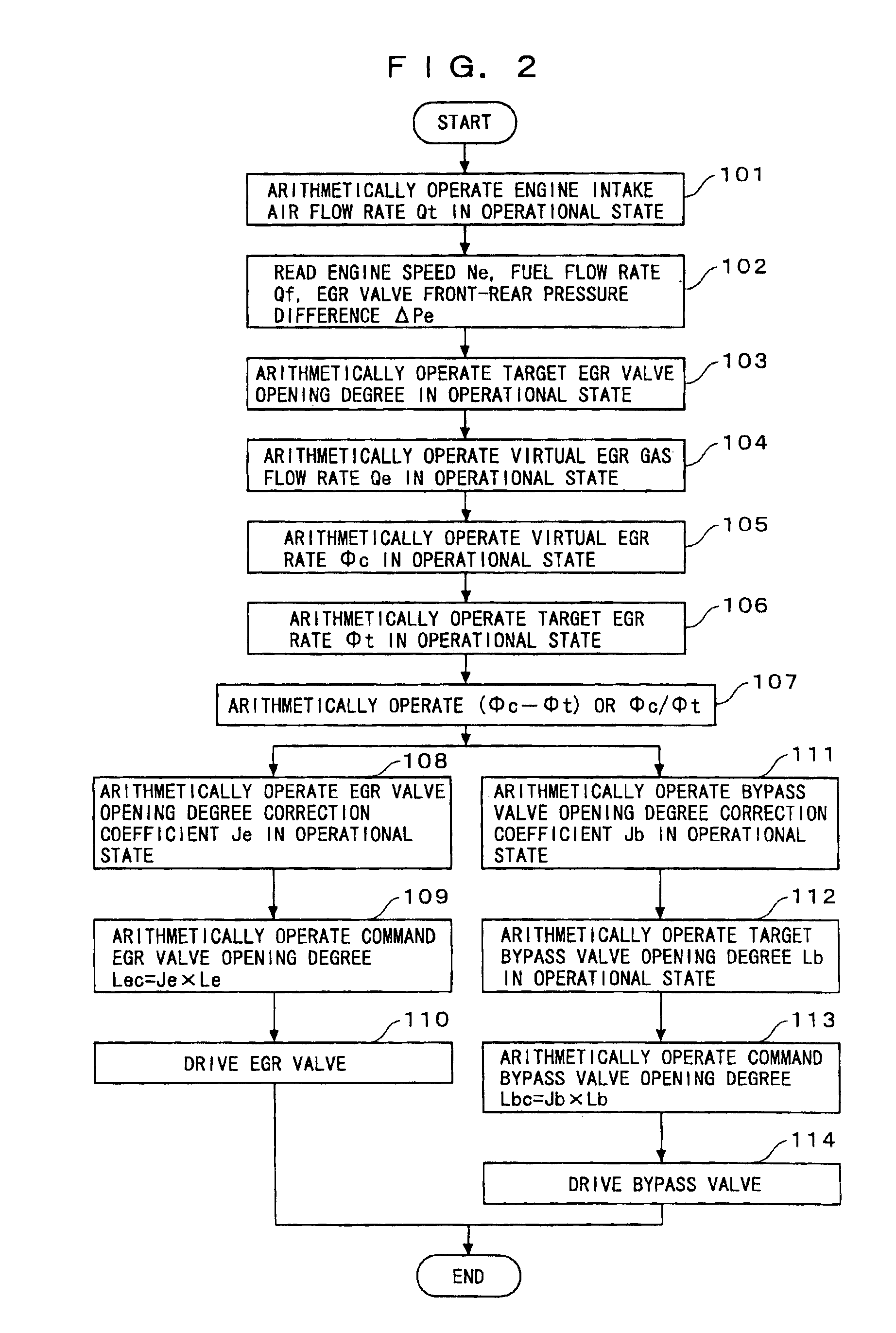
FIG. 1 is a block diagram showing an example of an EGR control system of an engine 1 with a supercharger. In FIG. 1, a compressor 2a of a supercharger 2 takes in air, and sends the air by pressure to an intake manifold 5 via an after-cooler 3 through an air supply pipe 4. The air sent by pressure is burned with a fuel injected by a fuel injection pump 7 inside an engine main body 6. An exhaust gas is sent to a turbine 2b of the supercharger 2 from an exhaust manifold 8 via an exhaust pipe 9, and after it drives the turbine 2b, it is released to an outside. The air supply pipe 4 is provided with a venturi 10, and a throat portion of the venturi 10 and the exhaust pipe 9 are connected by an EGR passage 11. The EGR passage 11 is provided with a cooler 12 and an EGR valve 13 for adjusting an opening area of the EGR passage 11...
PUM
 Abstract
Description
Claims
Application Information