Dressing of grinding tools for gear grinding

a gear grinding and dressing tool technology, applied in the direction of gear cutting machines, grinding machines, gear teeth, etc., can solve the problems of relative complexity of machine construction, difficult setting operations, and relatively poor access to dressing tools, and achieve high precision and rigidity.

Inactive Publication Date: 2005-03-22
REISHAUER
View PDF5 Cites 4 Cited by
  • Summary
  • Abstract
  • Description
  • Claims
  • Application Information

AI Technical Summary

Benefits of technology

The gear grinding machine according to the invention is provided with a dressing unit which can be infed by way of an infeed unit to a dressing position between a work fixture unit and a grinding tool fixture unit, where means is provided to position-and clamp the dressing unit with high precision and rigidity on the bed.
The gear grinding machine according to the invention makes it possible for the dressing unit to be located during dressing in an optimum position for dressing with respect to stiffness, thermal deformation of the machine, exploitation of the machine axes and accessibility. An advantage is that the same motion axes of the grinding tool can be used for grinding as well as for dressing, without the need for a turntable or pivoting tool holder. A further advantage is that when not in use the dressing tool can be brought into a dirt proofed position of rest, in which the dressing unit moreover hinders neither the grinding process nor the workpiece setting up process.

Problems solved by technology

This leads to a relatively complicated machine construction.
A further disadvantage is that the dressing tool is relatively poorly accessible, which makes setting operations difficult.
The disadvantage of this pivoting arrangement is the high expense.
A turntable of such stiffness and precision as are necessary for the dressing of a grinding worm and the grinding of gears demands resources which, on a machine with only one work spindle, are not justifiable.

Method used


Image

  • Dressing of grinding tools for gear grinding
  • Dressing of grinding tools for gear grinding
  • Dressing of grinding tools for gear grinding

Examples


Embodiment Construction

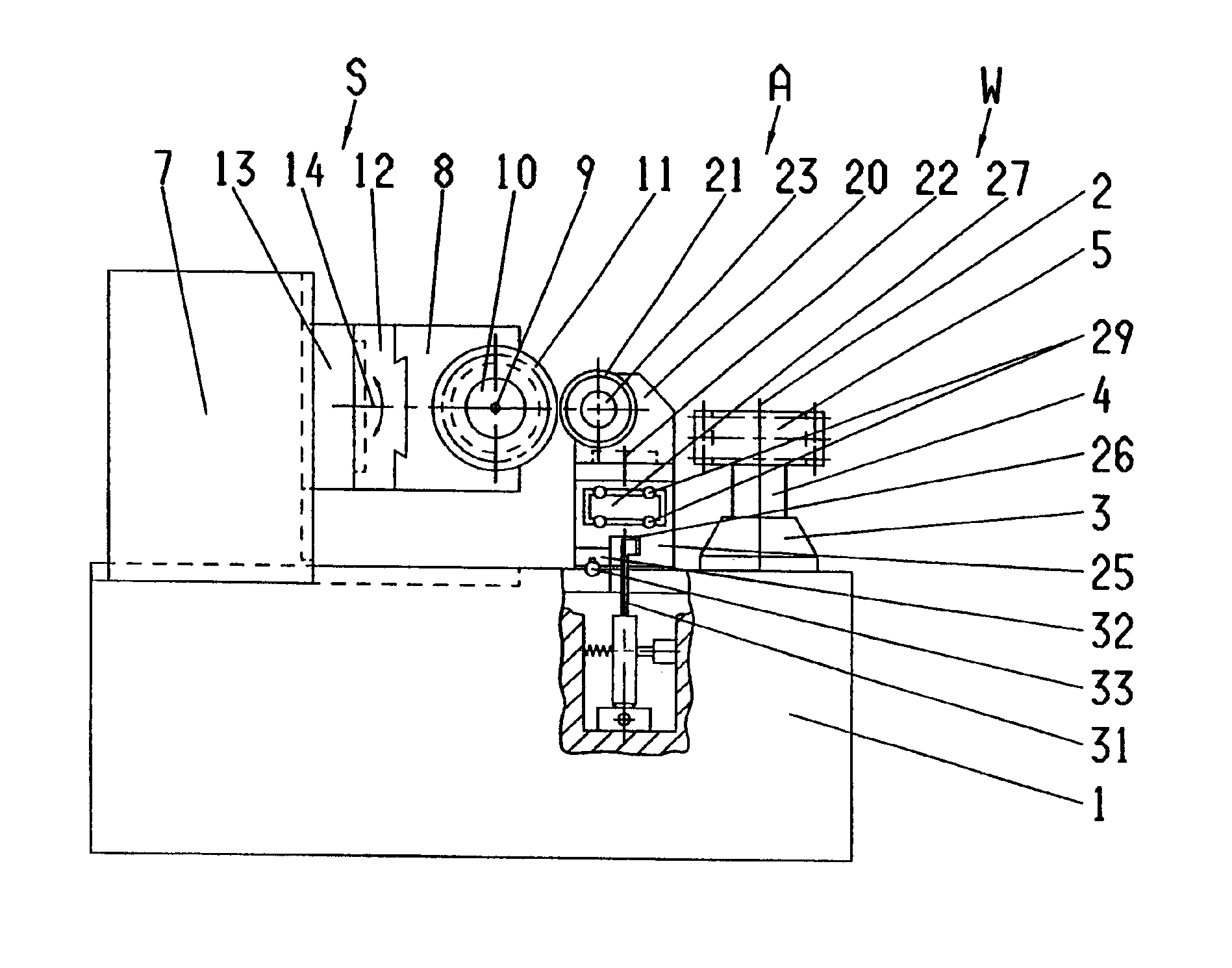
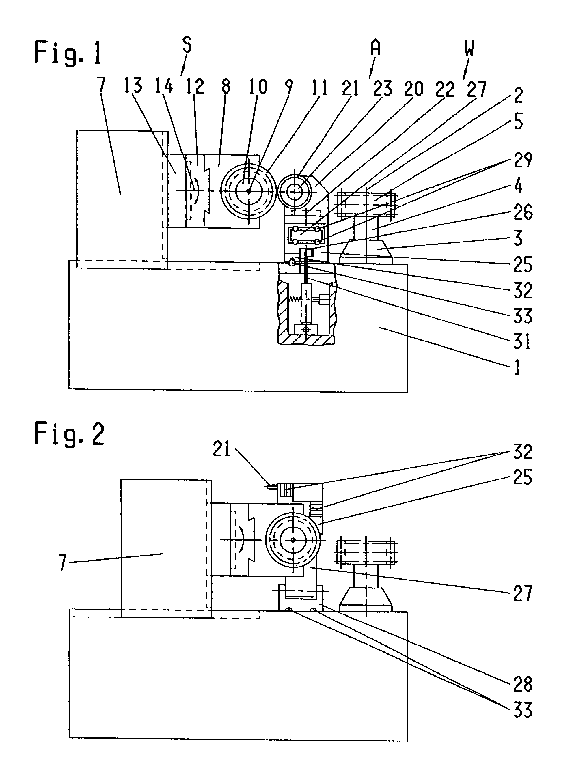
The tooth flank generation grinding machine shown in FIG. 1 comprises a machine bed 1 with a work fixture unit W and a grinding tool fixture unit S. The work fixture unit W consists of a work spindle 3 located in the machine bed 1 for rotation about a first axis 2, and a mandrel 4 for accommodating a workpiece 5.

The grinding tool fixture unit S consists of an infeed slide 7 located on the machine bed 1, which said slide is movable at right angles to the work spindle axis 2. The work fixture unit W and the grinding tool fixture unit S define a working area. In another constructional form the work fixture unit is arranged on an infeed slide and is movable relative to the grinding tool fixture unit.

Opposite the workpiece 5, and located in a grinding slide 8 for rotation about a second axis 9 is a grinding spindle 10 with a grinding tool attached to it, in this case a grinding wheel or a grinding worm 11. The grinding slide 8 is movable parallel to the grinding spindle axis 9 on a swive...


PUM

PropertyMeasurementUnit
pressureaaaaaaaaaa
abrasiveaaaaaaaaaa
stiffnessaaaaaaaaaa

Abstract

A dressing apparatus (20) attached to a dressing pedestal (25) of a tooth flank grinding machine is maneuverable by means of an advancer device (27) from a dust proof position of rest aside of the dressing position into an optimum dressing position lying between work spindle (3) and grinding worm (11). Here it can be clamped to the bed with high precision and rigidity. After dressing, it is maneuverable back to the position of rest, in which it hinders neither the grinding process nor the workpiece setting up process.

Description

TECHNICAL FIELDThe invention concerns a gear grinding machine. It concerns in particular a grinding machine with grinding worms for the continuous generation grinding of gears.STATE OF THE ARTIf these machines are employed with dressable grinding tools or grinding wheels, which is generally the case, they require a dressing unit by means of which the grinding wheel can be freshly dressed after grinding a certain number of workpieces. Thereby, after the loss in abrasive keenness and shape caused by the grinding process, the abrasive keenness and desired profile of the grinding wheel can be restored. This is usually performed by means of a rotating disc-shaped, hard abrasive coated dressing tool, with which material is removed from the peripheral surfaces of the grinding wheel in several dressing passes, until the grinding wheel profile is completely renewed.On a number of the known machines operating by the generation grinding method, the dressing tool is arranged on the side of the ...

Claims


Application Information

Patent Timeline
Patent Type & Authority Patents(United States)
IPC IPC(8): B23F23/00B23F23/12B24B53/06B24B53/085B24B53/075B23F5/04
CPCB23F23/1225B24B53/085B24B53/075
Inventor STOLLBERG, HORST
Owner REISHAUER
Why Eureka
Try Eureka