Heatable vehicle windshield with bus bars including braided and printed portions

a technology of bus bars and windshields, applied in the direction of heat exchangers, transportation and packaging, coatings, etc., can solve the problems of increasing the problem of heat dissipation of the inability to efficiently heat the heat-conductive coating, and the limited current carried by the side bus bar portion

Inactive Publication Date: 2005-03-22
GUARDIAN EURO S A R L
View PDF27 Cites 34 Cited by
  • Summary
  • Abstract
  • Description
  • Claims
  • Application Information

AI Technical Summary

Problems solved by technology

However, such an arrangement of the '234 patent is problematic in that in certain situations only a limited amount of current can be carried by the side bus bar portion (i.e., it would be desirable for the side bus bar portion to carry more current to / from the top bus bar portion than the '234 side bus bar portion enables).
The result of the '234 structure is that the heatable conductive coating cannot be efficiently heated.
This problem becomes even more pronounced with larger vehicle windows to be heated.
Unfortunately, because the braided bus bar is directly connected to the heatable coating, hot spots tend to be generated periodically at different points in the coating where the bus bar is electrically connected thereto.
It can be seen that it is not desirable for a braided bus bar to be directly electrically connected to an underlying heatable coating.
Moreover, the '932 utilizes braided bus bars on both sides of the window, thereby failing to address and / or recognize the problem(s) discussed above.
Because the '328 patent uses bus bars on both sides of the window, it fails to address of remedy the problems in the art discussed above.
Moreover, single strand copper wires are typically not capable of carrying enough current to remedy the problems with the '234 patent discussed above.

Method used


Image

  • Heatable vehicle windshield with bus bars including braided and printed portions
  • Heatable vehicle windshield with bus bars including braided and printed portions
  • Heatable vehicle windshield with bus bars including braided and printed portions

Examples


Embodiment Construction

An object of this invention is to provide a heatable vehicle window including bus bar portion(s) which efficiently supplying electric current to / from a continuous heatable coating.

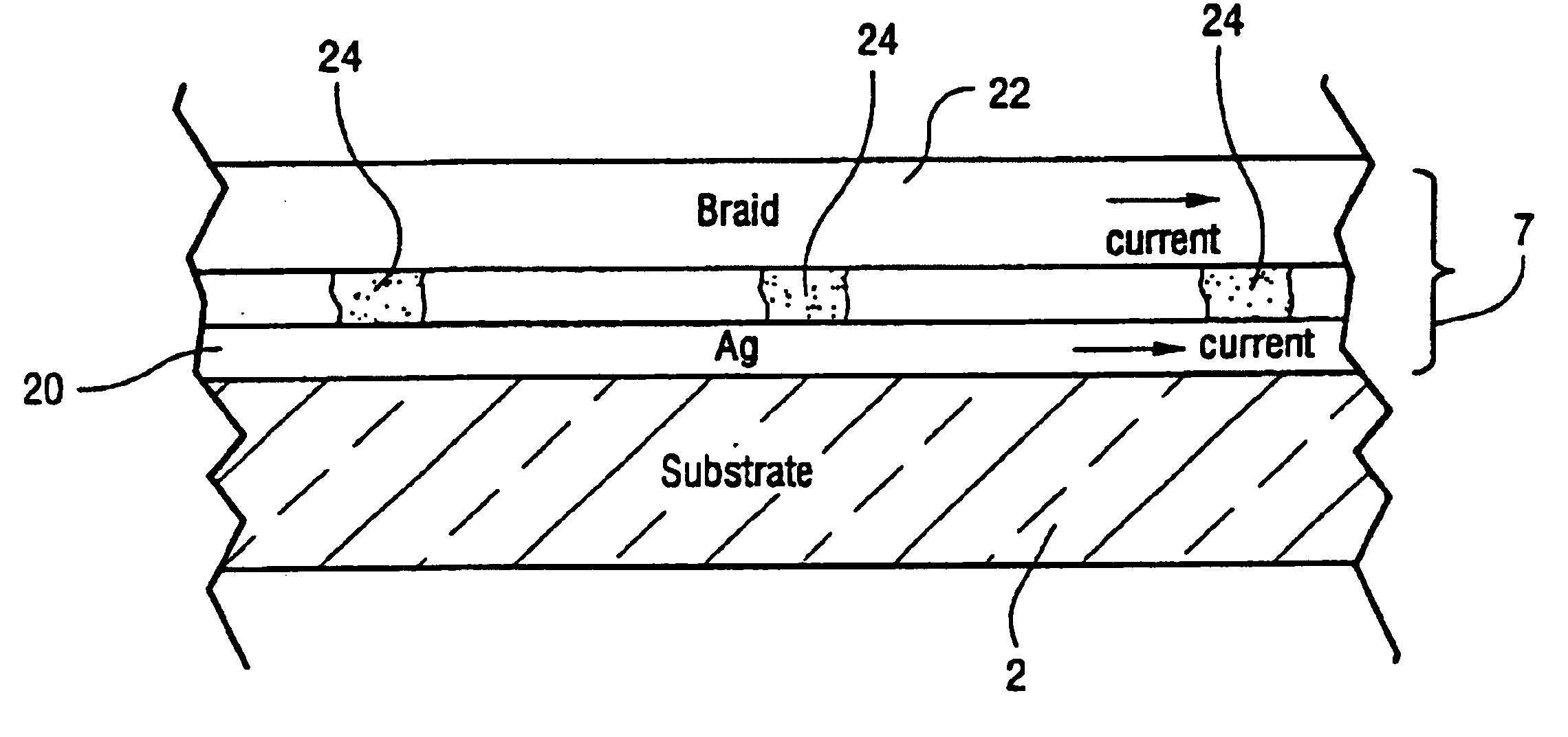
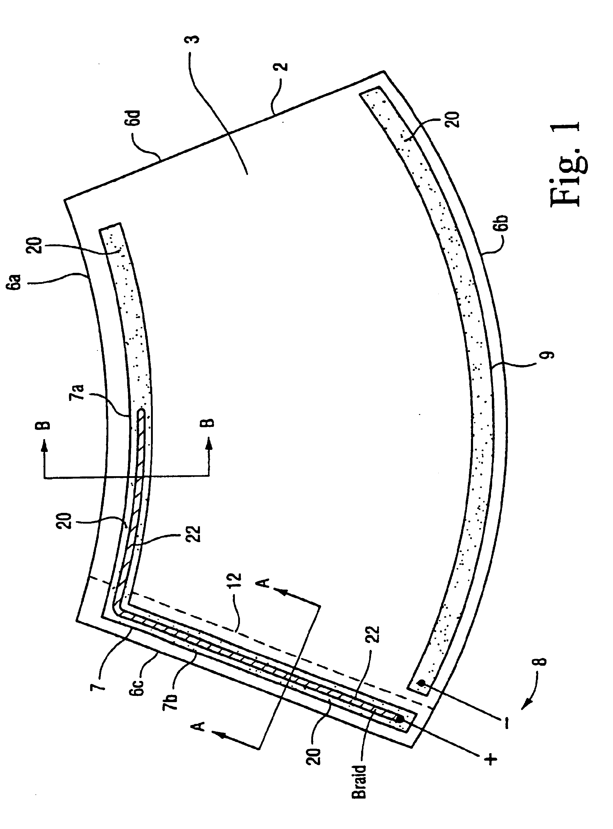
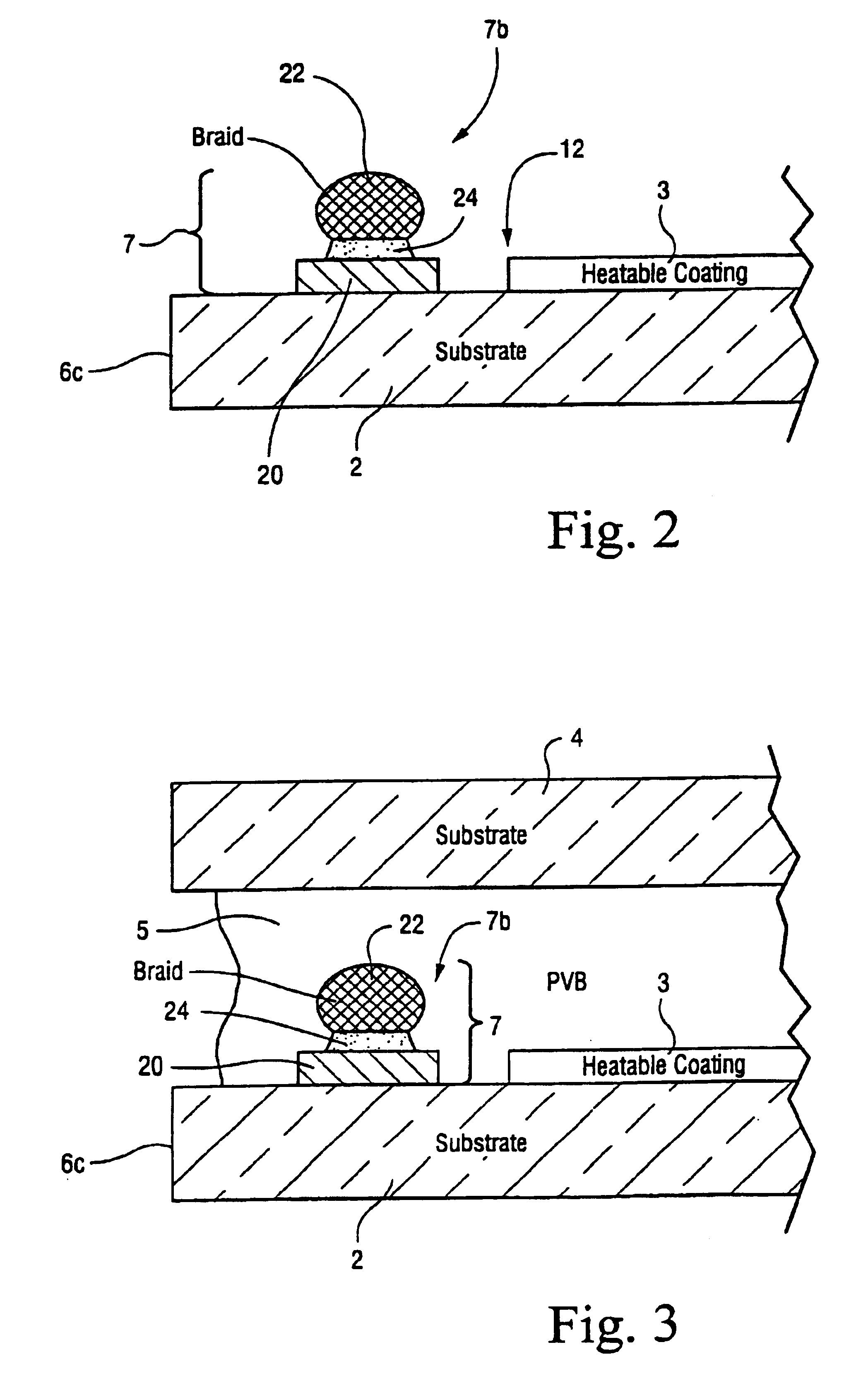
Another object of this invention is to provide a bus bar portion for supplying electric current to / from a heatable coating, wherein the bus bar portion includes both (a) an underlying conductive base portion, and (b) an overlying conductive braid portion that is conductively attached to the conductive base portion along a length portion of the bus bar portion. In this respect, the braid portion significantly increases the current capacity of the bus bar portion so that if desired, such a bus bar portion for supplying current to / from a top bus bar portion need only be provided along one of the two sides of the window assuming that the terminal connections are at the bottom of the window.

Another object of this invention is to fulfill one or more of the aforesaid objects and / or needs.

Certain example embodimen...


PUM

PropertyMeasurementUnit
transparentaaaaaaaaaa
sheet resistanceaaaaaaaaaa

Abstract

A heatable window (e.g., vehicle windshield) includes a heatable layer including one or more conductive layers. The heatable layer may be a single layer conductive coating, or alternatively may be a multi-layer heatable coating including one or more dielectric layer(s) in addition to one or more heatable conductive layer(s). Bus bars are provided so that a voltage may be applied across at least one conductive layer of the coating, in order to heat the layer so that the coating generates heat for defogging, deicing and/or desnowing the window. At least a portion of one of the bus bars includes both an underlying conductive base layer portion, and an overlying conductive braid portion that is conductively attached to the conductive base portion. The braid portion significantly increases the current capacity of the bus bar portion if so desired.

Description

This invention relates to a heatable vehicle window (e.g., heatable vehicle windshield or any other type of heatable vehicle window). More particularly, this invention relates to a heatable vehicle window including at least one bus bar, wherein the bus bar includes both a printed portion (e.g., silk-screen silver (Ag) inclusive portion) and a braided portion provided over and in electrical communication with the printed portion.BACKGROUND OF THE INVENTIONHeatable vehicle windows are known in the art, and typically include top and bottom conductive bus bars in electrical contact with a transparent conductive coating including an electro conductive layer. The electro conductive layer generates heat when electric current is passed therethrough via the bus bars. In such a manner, snow and ice may be melted from vehicle windows such as windshields, backlites, and / or the like. Windows may also be defogged in such a manner. Moreover, since terminal connections (e.g., via jumper wires) for ...

Claims


Application Information

Patent Timeline
Patent Type & Authority Patents(United States)
IPC IPC(8): H05B3/84B32B17/10
CPCB32B17/10036H05B3/84B32B17/10174H05B2203/016
Inventor SOL, JEAN-MARCBIZZARI, CHRISTIAN
Owner GUARDIAN EURO S A R L
Why Eureka
Try Eureka