Method of measuring length and coordinates using laser tracking interferometric length measuring instruments

a technology of laser tracking and measuring instruments, applied in the direction of instruments, distance measurements, polarising elements, etc., can solve the problems of many problems that still need to be solved, no gage having that kind of precision, and giving rise to an anti-abbe's error

Inactive Publication Date: 2005-03-22
NAT INST OF ADVANCED IND SCI & TECH
View PDF10 Cites 9 Cited by
  • Summary
  • Abstract
  • Description
  • Claims
  • Application Information

AI Technical Summary

Benefits of technology

As described in the above, in the laser interferometric length measuring instrument according to the present invention, a laser beam is directed at the center of the reflector of an articulating optical lever provided on the optical path of the laser interferometric optical system. The reflected laser beam can be directed in a desired direction by controlling the optical lever. While controlling the optical lever to have the reflected laser beam track a retroreflector that is the measurement object, displacement of the interferometric origin of measurement can be kept very small, even if the attitude of the optical axis is changed. By using an articulating optical lever having a hemisphere with a sphericity of 0.1 μm and an R-H of 0.1 μm, origin of measurement based eccentricity can be kept to a maximum of 1.0 μm.

Problems solved by technology

However, with the existing level of technology, there is no gage having that kind of precision.
Interferometric measurement using a frequency-stabilized He—Ne laser is a method suited to measurement of such a calibration gage, but it entails many problems that still need to be resolved.
With respect to the accuracy of single-axis measurement of a coordinate measuring machine along the X axis, Y axis and Z axis, interferometric measurement using the He—Ne laser is possible, but the coordinate measurement resulting from the X, Y, Z travel gives rise to an anti-Abbe's error from the perpendicularity between the three axes and the yawing and pitching.
Measuring all error takes far too long to be practical.
However, with the configuration of a prior art measuring instrument, keeping the eccentricity to not more than 1.0 μm is difficult.
If the attitude of the telescope is changed by error at the point of intersection of the three axes, the approximate 3-axis intersection point will move eccentrically, giving rise to a primary error in the length measurement.

Method used


Image

  • Method of measuring length and coordinates using laser tracking interferometric length measuring instruments
  • Method of measuring length and coordinates using laser tracking interferometric length measuring instruments
  • Method of measuring length and coordinates using laser tracking interferometric length measuring instruments

Examples


Embodiment Construction

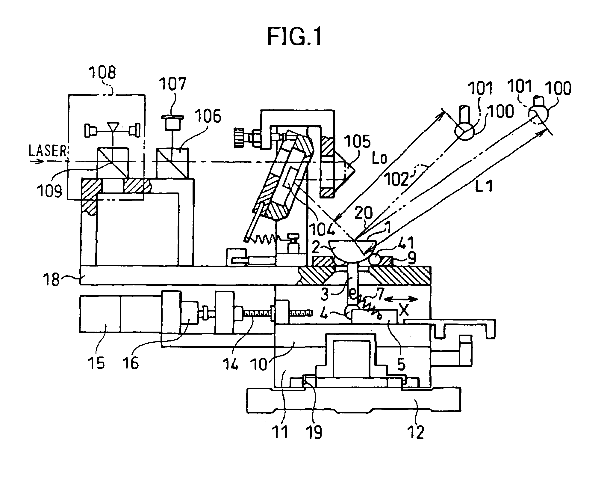
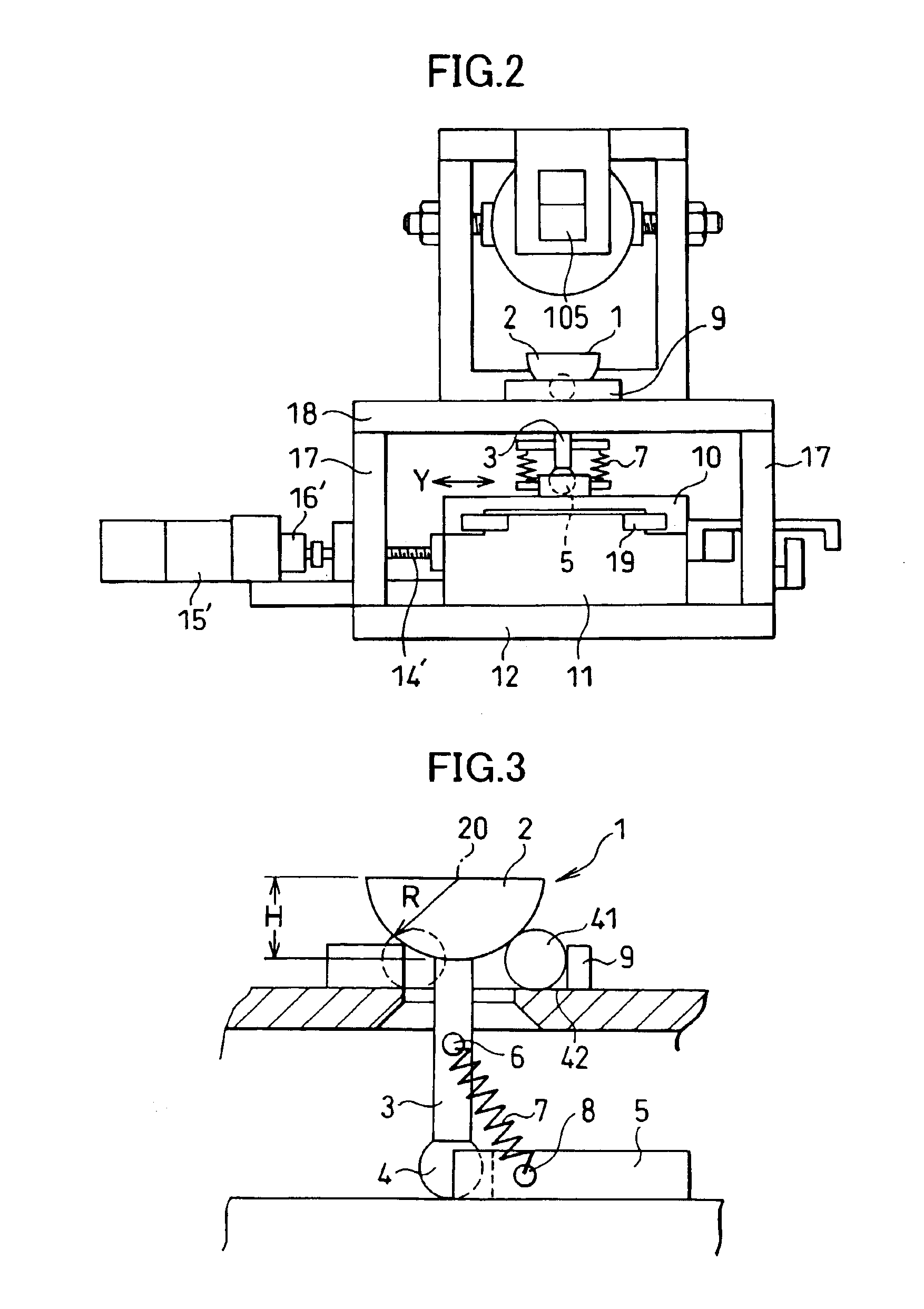
FIGS. 1 and 2 show a laser tracking interferometric length measuring instrument according to an embodiment of the present invention. Reference numeral 1 denotes the basic structure of an articulating optical lever used in the above length measuring instrument, which also includes a hemisphere 2, a three-ball seat plate 9 and a ball 4, details of which are shown in FIGS. 3, 4 and 5.

In FIGS. 3 and 4, the hemisphere 2 was prepared by cutting a steel bearing ball in half plus a slight allowance for finishing, and the cut surface was lapped to give the hemisphere a thickness H equal to the radius R. As the hemisphere 2, there may be used a glass hemisphere finished in the same way as a steel one. Each steel ball-bearing ball that was actually selected had a sphericity that was within 0.1 μm, and was cut to form a hemisphere which was lapped to an R-H value of 0.1 μm. The sphericity of 0.1 μm plus the R-H value of 0.1 μm is 0.2 μm, so when the hemisphere is set in place on a three-ball se...


PUM


Abstract

A laser tracking interferometric length measuring instrument has a laser source and a tracking articulating optical lever provided on an optical path of an interferometric optical system. To track a retroreflector, the optical lever reflects a laser beam at the retroreflector, which reflects the beam back to the optical lever. This beam is reflected onto a quadrant photodiode. An attitude control means is used to control the attitude of the optical lever so that the laser beam reflected by the optical lever falls on the neutral point of the photodiode.

Description

BACKGROUND OF THE INVENTION1. Field of the InventionThe present invention relates to a laser tracking interferometric length measuring instrument that uses a laser beam to track the traveling distance of retroreflectors traveling in X, Y, Z three-dimensional space while performing trilateration, and to a method of measuring length and coordinates using the length measuring instrument.2. Description of the Prior ArtThere are known measuring instruments using optical interferometry. These instruments were developed for triangulation applications, and incorporate an optical interferometry system in the lens-barrel of the instrument's telescope to measure the traveling distance of mirrors. This technology is used in construction engineering works and other areas of industry that employ the triangulation method, with laser interferometry being used for the measurements that were formerly performed using a tape measure, because optical interferometry provides a higher measurement accuracy...

Claims


Application Information

Patent Timeline
Patent Type & Authority Patents(United States)
IPC IPC(8): G01B11/00G01C3/06
CPCG01B11/002G01B11/007G01B11/005
Inventor OSAWA, SONKOTAKATSUJI, TOSHIYUKIKUROSAWA, TOMIZONOGUCHI, HIRONORIHONG, JIANG
Owner NAT INST OF ADVANCED IND SCI & TECH
Why Eureka
Try Eureka