Screens and methods for displaying information

a technology of information screens and screens, applied in the field of optical systems, can solve the problems of inability to conveniently roll an inflexible projection screen, fading or washout of the projected image, and the rear projection screen is sensitive to ambient lighting conditions, and achieves high contrast, high resolution, and easy mounting.

Inactive Publication Date: 2005-03-22
3M INNOVATIVE PROPERTIES CO
View PDF64 Cites 54 Cited by
  • Summary
  • Abstract
  • Description
  • Claims
  • Application Information

AI Technical Summary

Benefits of technology

The present invention preferably comprises a high contrast, high resolution, flexible, rear projection screen along with a removable adhesive which can be mounted easily on a window or any other transparent surface to form an imaging surface for a rear projection display.

Problems solved by technology

As a result, it is not possible to conveniently roll an inflexible projection screen in the fashion that a diploma or map may be rolled as it will damage the screen.
Screens that are merely translucent tend to strongly reflect ambient light incident on the front, viewing side, resulting in fading or washout of the projected image.
As a result, this rear projection screen is sensitive to ambient lighting conditions.
Many televisions used for this type of advertising are permanently installed or very large and heavy and, as a result, are not portable.
Installation of floor or ceiling mounted systems requires significant resources.
Complicated or time consuming installation procedures contribute to the cost of the system.
While rear projection systems are available that are self-contained units, such self-contained rear projection systems typically include bulky framework and housing elements that render the systems difficult to reposition.
Rear projection systems with large screens also tend to be quite heavy, further contributing to difficulties associated with transporting and installing the optical system.
This film is very selective about the direction from which it receives the light, thereby complicating installation.
The screen is transparent and very expensive.
The screen lacks an efficient ambient light absorbing layer, hence it is susceptible to washout in brightly lit conditions.
These bright projectors are expensive to purchase.
They are also expensive to maintain due to short lamp lives.
A permanently installed optical system runs the risk of becoming commonplace.
This is a problem as purchasing decisions are often made at the point of purchase.

Method used


Image

  • Screens and methods for displaying information
  • Screens and methods for displaying information
  • Screens and methods for displaying information

Examples


example 1

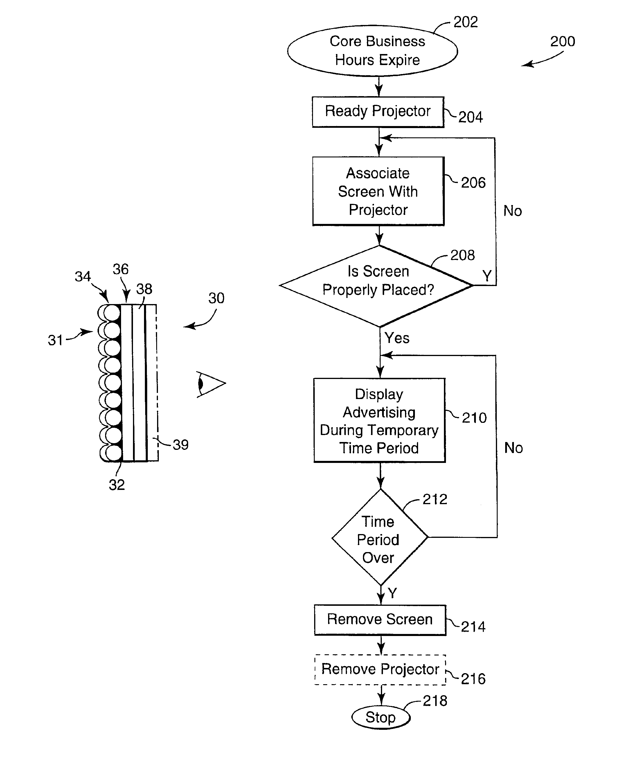
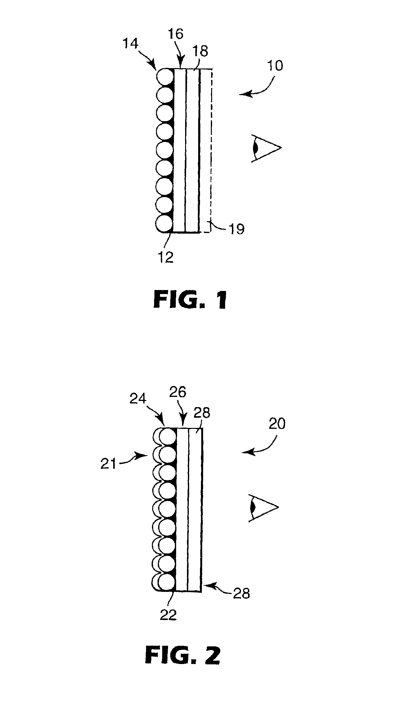
A monolayer glass beaded film similar to that shown in FIG. 15 B was provided. The film comprises a monolayer of glass bead of approximately 65 micrometers, an opaque black matrix (urethane and carbon black) and a polyvinyl chloride substrate. The beads had a refractive index of about 1.9. The film is generally available from Minnesota Mining and Manufacturing Company of St. Paul, Minn. under the name BePF 120 beaded film. The screen was attached to a glass window using Scotch Glue Stick Restickable Adhesive (3M catalog #6314) generally available from Minnesota Mining and Manufacturing Company of St. Paul, Minn. The film plus the adhesive was approximately 6 mils thick. The adhesive was not coated over the entire viewing surface of the screen. Instead, the adhesive was only placed on the four comers of the beaded film screen. The assembly provided a secure, releasable attachment to the window.

The assembly was coupled to a Toshiba LCD Data Projector, number TLP 710 and video was view...

example 2

Beaded Film Laminated to PVC Film

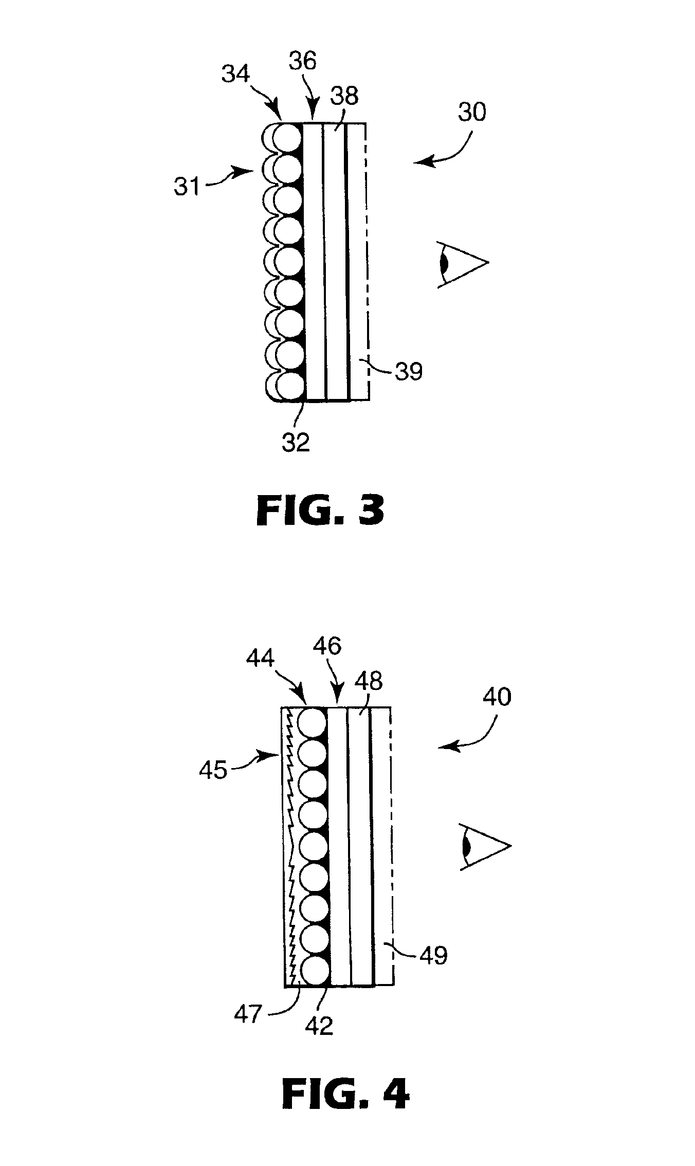
A monolayer glass beaded film similar to that described in Example 1 was provided. The film comprises a monolayer of glass bead of approximately 65 micrometers in diameter, an opaque black matrix (urethane and carbon black) and a polyvinyl chloride substrate. The film is generally available from Minnesota Mining and Manufacturing Company of St. Paul, Minn. under the name BePF 120 beaded film. A 10 mil thick plasticized PVC film (KGC193 Clear PVC Film from Achilles USA, Inc.) was laminated to the non-beaded side of the beaded film using the pressure sensitive adhesive 3M Opt-1 Laminating adhesive (also known as Bonding Systems Division 9483 adhesive) available from 3M. The screen was approximately 20 mils thick. This assembly was pressed against a glass window to provide a secure, releasable and reusable attachment of the screen to the window. The material is also believed to be washable.

example 3

Beaded Film Laminated with Ethylene Vinyl Acetate

A monolayer glass beaded film similar to that described in Example 1 was provided. The film comprises a monolayer of glass bead of approximately 65 micrometers in diameter, an opaque black matrix (urethane and carbon black) and a polyvinyl chloride substrate. The film is generally available from Minnesota Mining and Manufacturing Company of St. Paul, Minn. under the name BePF 120 beaded film. An ethylene vinyl acetate film (EVA Elvax from Dupont, 5 mils thick) was laminated to the polyvinyl chloride substrate. No additional adhesive was needed to attach the BePF 120 to the EVA. The screen was approximately 11 mils thick. The assembly provided a secure, releasable and reusable attachment of the screen to the window. Adhesion by static cling is believed to hold the EVA film firmly to the BePF 120 and provides attachment of the assembly to the window. The material is also believed to be washable.


PUM


Abstract

A flexible screen with a mechanism for releasably attaching the screen to a transparent door or window is disclosed. A method of use is also disclosed.

Description

FIELDThis invention relates generally to optical systems for temporarily providing information and more particularly to flexible, transmissive screens with high ambient light rejection for use in rear projection systems.BACKGROUNDRear projection screens transmit an image projected onto the rear of the screen into a viewing space. A rear projection screen may be a sheetlike optical device with a relatively thin viewing layer that is placed at an image surface of the projector. Examples of rear projection displays are disclosed in PCT WO 99 / 064927, PCT WO 99 / 13378 and EP 783 133.Projection screens are often constructed of rigid materials such as glass or a semi-rigid, transparent polymeric material. As a result, it is not possible to conveniently roll an inflexible projection screen in the fashion that a diploma or map may be rolled as it will damage the screen. Examples of a typical prior art rigid projection screens comprise the DA series of diffusion screens from DA-Lite. Rigid pro...

Claims


Application Information

Patent Timeline
Patent Type & Authority Patents(United States)
IPC IPC(8): G03B21/62G03B21/00G03B21/10G03B21/14G03B21/28G09F19/18H04N5/74
CPCG03B21/10G03B21/625G03B21/28G03B21/62
Inventor GEHRING, THOMAS R.GRAETZ, MICHAEL L.PIEPEL, ANDREW J.SCHULEMAN, MARK L.YARINA, KENNETH L.
Owner 3M INNOVATIVE PROPERTIES CO
Why Eureka
Try Eureka