Power saving in communication terminals

a technology of communication terminals and power saving, applied in the field of communication terminals, can solve the problems of no reduction in reception time and successful decoding rate, and achieve the effect of reducing the average current consumption of a communication terminal

Inactive Publication Date: 2005-03-22
INTEL CORP
View PDF10 Cites 33 Cited by
  • Summary
  • Abstract
  • Description
  • Claims
  • Application Information

AI Technical Summary

Benefits of technology

[0009]An aspect of some preferred embodiments of the invention to relates to reducing the average current consumption of a communication terminal during an idle mode.

Problems solved by technology

Thus, there is no reduction in successful decoding rates due to the reduction in the reception time.

Method used


Image

  • Power saving in communication terminals
  • Power saving in communication terminals
  • Power saving in communication terminals

Examples


Embodiment Construction

orming an additional decoding attempt if the decoding was not successful. Preferably, the additional decoding attempt is performed without altering values of any of the bits.

BRIEF DESCRIPTION OF FIGURES

[0043]The invention will be more clearly understood by reference to the following description of preferred embodiments thereof in conjunction with the figures, in which:

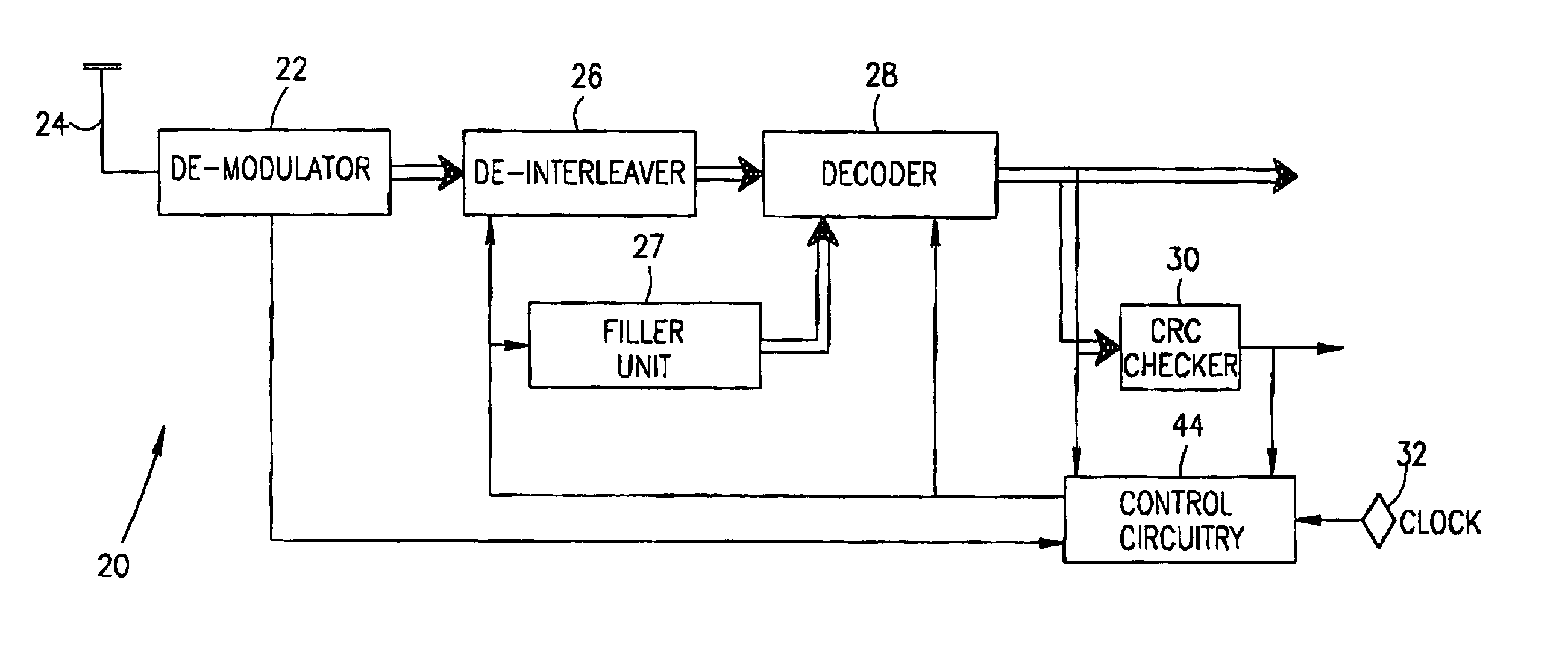
[0044]FIG. 1 is a simplified schematic illustration of a receiver, in accordance with a preferred embodiment of the present invention;

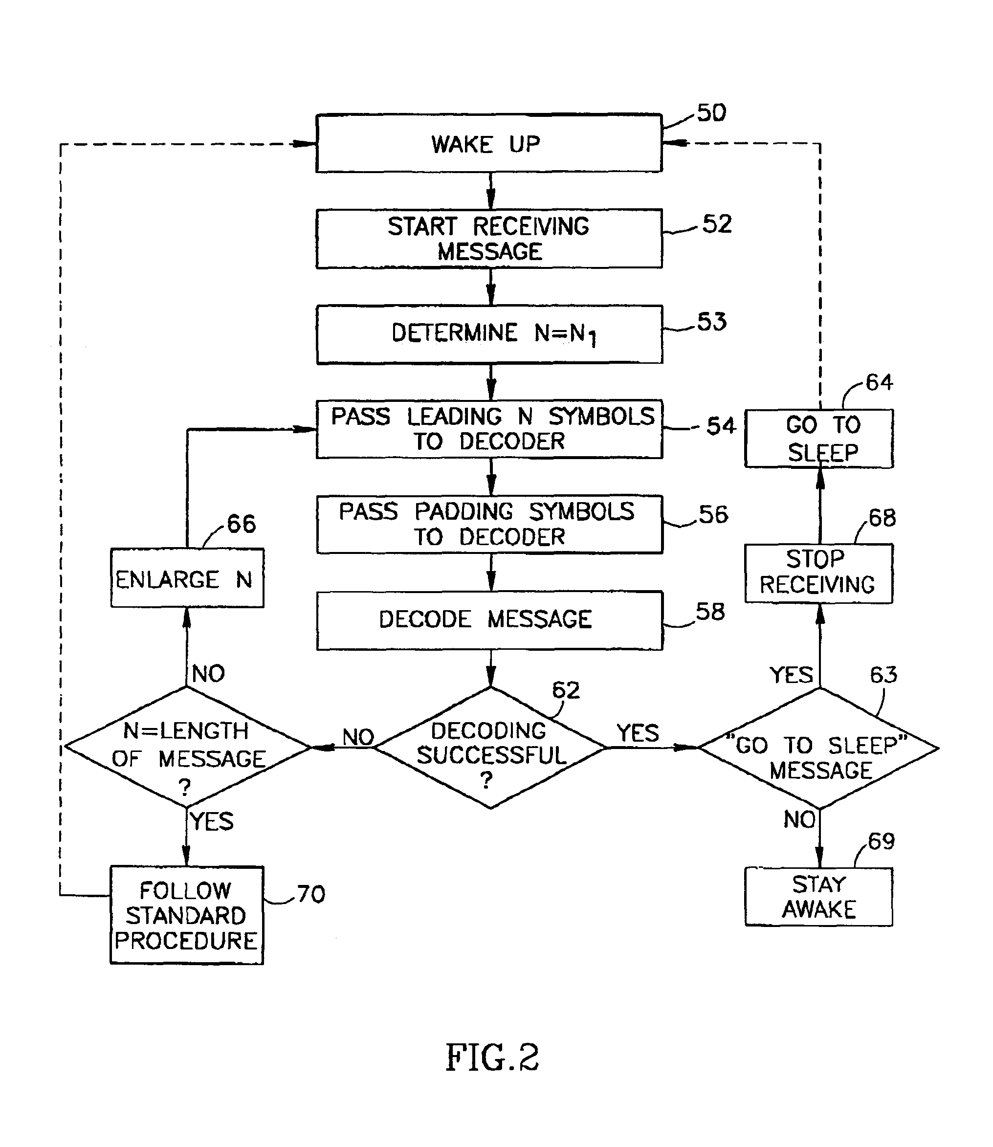
[0045]FIG. 2 is a flow chart of the actions performed by the receiver of FIG. 1, in accordance with a preferred embodiment of the present invention;

[0046]FIG. 3 is a schematic graph of the operation timings of the receiver of FIG. 1, in accordance with a preferred embodiment of the present invention; and

[0047]FIG. 4 is a schematic illustration of a structure of a decoded message commonly received by the receiver of FIG. 1, in accordance with a preferred embodiment of the present inventio...


PUM


Abstract

A method of receiving messages by a communication terminal. The method includes receiving symbols of a frame of a transmitted encoded message, and decoding the frame based on fewer received symbols than the number of symbols in the frame.

Description

FIELD OF THE INVENTION[0002]The present invention relates to communication terminals such as cellular phones and pagers and in particular to methods for receiving and decoding messages by communication terminals.BACKGROUND OF THE INVENTION[0003]Messages transmitted to cellular phones are encoded in order to reduce the chances that noise will corrupt the message. The message comprise a plurality of bits which are either ‘0’ or ‘1’. The encoding of the message usually includes adding redundancy (i.e., making the encoded message longer than the original message), involving symbol dependency (i.e., making the value of each symbol in the encoded message a function of a plurality of bits in the original message) and interleaving the message (i.e., mixing the order of the symbols in the encoded message).[0004]Normally, each symbol in the received message is represented in the receiver, before decoding, by a word which represents the chance that the symbol is a logical “1”. A high positive ...

Claims


Application Information

Patent Timeline
Patent Type & Authority Patents(United States)
IPC IPC(8): H04L27/06H04B1/16H04L1/00H04W52/02
CPCH04L1/0045H04L1/0061H04W52/0225H04L1/0071Y02B60/50Y02D30/70
Inventor YELLIN, DANIELLEVY, SHARONBEN-ELI, DAVIDPICK, JACOB
Owner INTEL CORP
Why Eureka
Try Eureka