Direct conversion receiver, mobile radio equipment using the same, and RF signal receiving method

a technology of direct conversion and mobile radio equipment, applied in the direction of electrical equipment, antennas, electrical long antennas, etc., can solve the problems of high receive error rate, demodulation accuracy deterioration, and difficulty in normal reception, so as to shorten the waiting time, shorten the operating time of the receiver, and shorten the time needed

Inactive Publication Date: 2005-03-22
PANASONIC CORP
View PDF6 Cites 26 Cited by
  • Summary
  • Abstract
  • Description
  • Claims
  • Application Information

AI Technical Summary

Benefits of technology

The present invention has been developed with a view to eliminating the above-mentioned problems, and it is therefore an object of the invention to provide a direct conversion receiver capable of shortening the time for the settlement of the automatic gain control at the wait operation and of preventing the degradation of the demodulation accuracy in a call, a mobile radio equipment using this direct conversion receiver, and an RF signal receiving method.
With this arrangement, the gain control interval can be shortened by decreasing the time constant of the second low pass filter, thereby accomplishing fast settlement of the automatic gain control. Moreover, since the time constant of the second low pass filter is increased after the settlement of the automatic gain control, it is possible to lower the cutoff frequency of the high-pass characteristic of the received baseband unit, which results in reducing the receive error rate.
With this arrangement, since the variation of the gain control signal becomes gentle and the gain control can be implemented to permit the follow-up of the offset compensating unit, the DC level variation does not develop in a signal outputted from the receive baseband unit, thereby enhancing the demodulation accuracy.
Since the time of the sleep cancellation to the quadrature demodulator or the receive baseband unit is a timing at which the output frequency of the frequency synthesizer becomes stable and a smaller pulse width of the signal for the control of the switch is employable, the reduction of the circuit scale of the counter is feasible.
With this arrangement, while the frequency synthesizer conducts the frequency switching operation, the quadrature demodulator or the receive baseband unit is in the sleep condition, and this can shorten the operating time of the receiver which is in the wait operation.
Since this arrangement can shorten the time needed for the settlement of the automatic gain control during the wait operation, which shortening the operating time of the receiver which is in the wait operation and shortening the wait time. Moreover, because of no DC variation at the gain control during call, no deterioration of the call quality occurs.

Problems solved by technology

Even if these offset voltages are several mV, each of the receive baseband units 2 and 3 has a cascade gain of several tens dB, which can make difficult the normal reception because of the occurrence of circuit saturation in the control unit 4.
That is, the receive error rate becomes high.
In the above-described direct conversion receiver, when the signals I, Ix, Q and Qx vary in DC at the gain control of the gain control amplifier 22, a problem arises in that demodulation accuracy deteriorates.
In addition, in the case of the gain control for each receive slot during calls or the like, difficulty is encountered in avoiding the deterioration of the demodulation accuracy due to the DC variation.
Moreover, in a case in which this direct conversion receiver is employed for a mobile radio equipment such as a portable telephone, since the settlement of the automatic gain control during a queue operation takes time, there occurs a problem of prolonging the operation time of the receiver during the wait operation and shortening the wait time.
Still moreover, the call quality degrades due to the DC variation at the gain control in a call.

Method used


Image

  • Direct conversion receiver, mobile radio equipment using the same, and RF signal receiving method
  • Direct conversion receiver, mobile radio equipment using the same, and RF signal receiving method
  • Direct conversion receiver, mobile radio equipment using the same, and RF signal receiving method

Examples


Embodiment Construction

Referring to the drawings, a detailed description will be given hereinbelow of an embodiment of the present invention. Incidentally, the same parts as those of the conventional direct conversion receiver shown in FIG. 5 are marked with the same reference numerals, and the description thereof will be omitted for brevity.

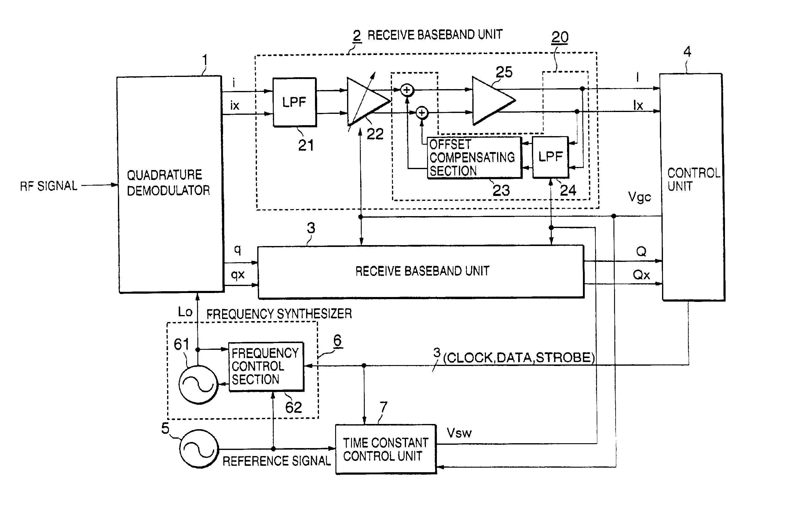
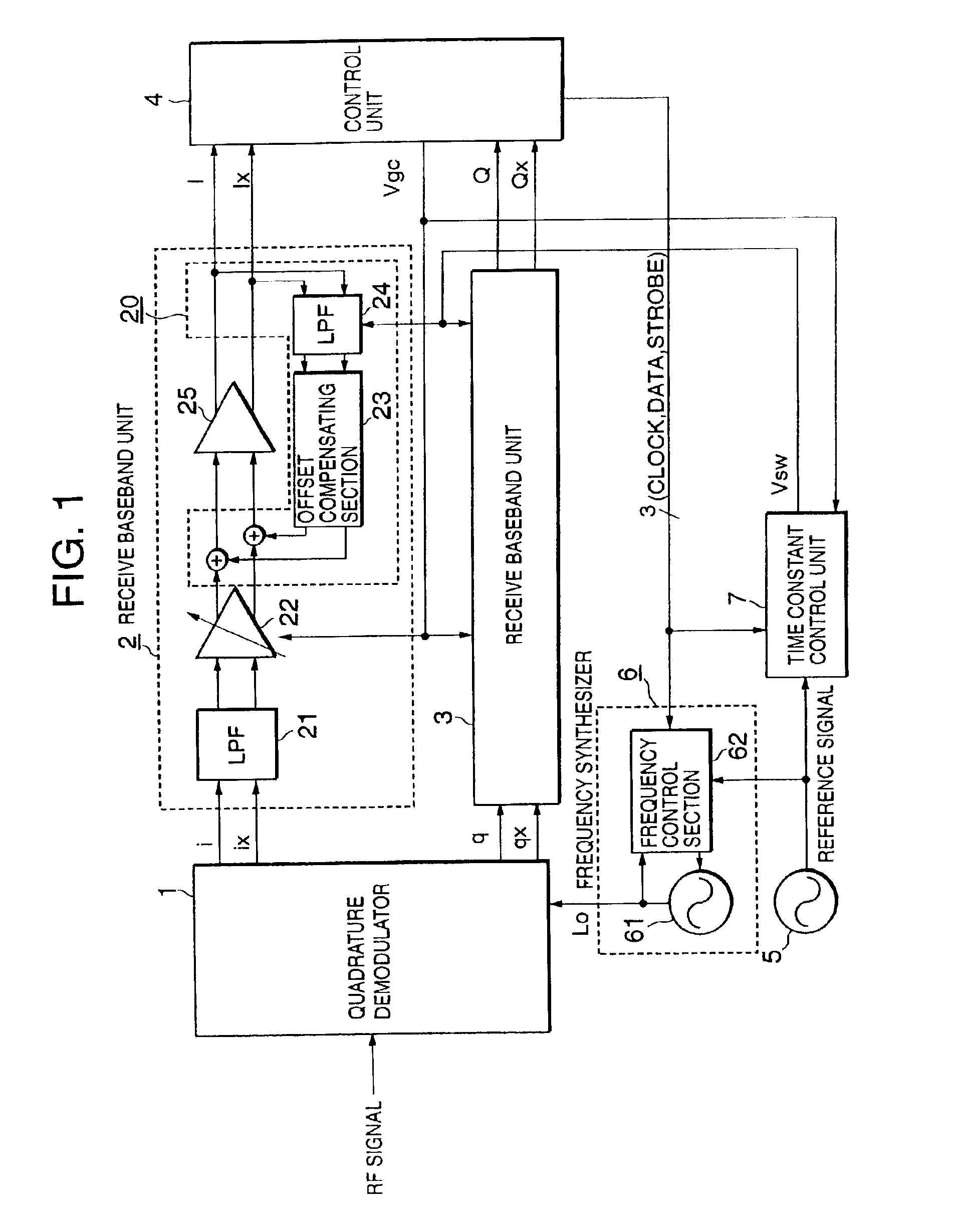
FIG. 1 is a block diagram showing a direct conversion receiver according to an embodiment of the present invention. As a feature of this direct conversion receiver different from the conventional direct conversion receiver shown in FIG. 5, a clock signal (CLOCK), a data signal (DATA), a strobe signal (STROBE) and a gain control signal Vgc are outputted from a control unit 4 to a time constant control unit 7 and a reference signal is outputted from a reference signal source 5 to the time constant control unit 7 while a signal Vsw is fed from the time constant control unit 7 to a low pass filter 24 constituting each of receive baseband units 2 and 3.

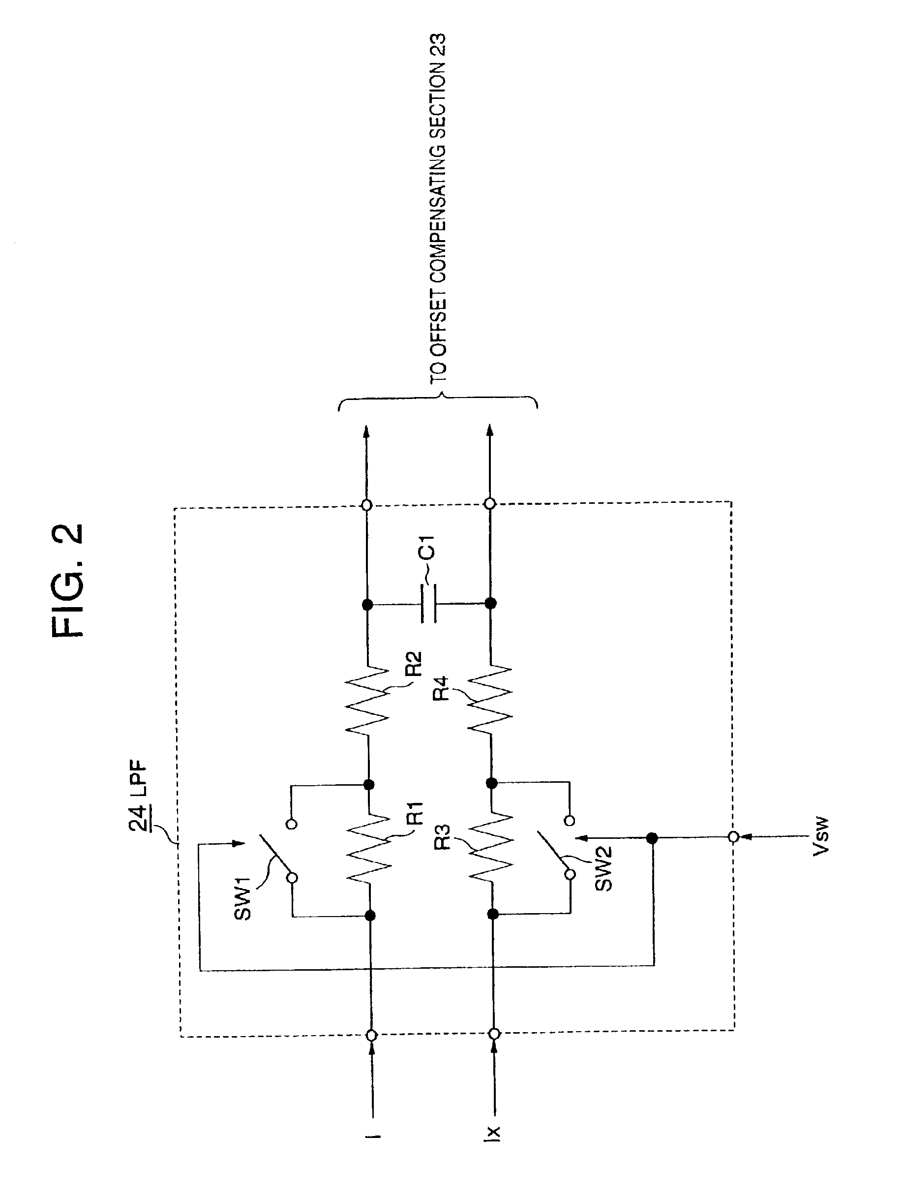
FIG. 2 is an illustr...


PUM


Abstract

In a direction conversion receiver, a quadrature demodulator produces differential signals in a baseband on the basis of a local signal of a frequency synthesizer, with the differential signals being inputted through a first low pass filter, a gain control amplifier and an amplifier to a control unit and a direct current component between the differential signals being extracted in a second low pass filter. In addition, an offset compensating section reduces an offset voltage while the control unit outputs a control signal for the control of the gain control amplifier. The second low pass filter includes a time constant circuit for determining a time constant through the use of resistors and a capacitor, and a time constant changing section. A time constant control unit controls the time constant changing section for a predetermined period of time after the control unit outputs data for the change of a frequency of the local signal so that the time constant of the time constant circuit decreases. This shortens the time needed for the settlement of automatic gain control and prevents the deterioration of demodulation accuracy during a call.

Description

BACKGROUND OF THE INVENTION1) Field of the InventionThe present invention relates to a direct conversion receiver for use in mobile radio equipment or the like, a mobile radio equipment using this direct conversion receiver, and a method of receiving an RF signal.2) Description of the Related ArtFIG. 5 is a block diagram showing a circuit arrangement of a conventional typical direct conversion receiver. In this illustration, a quadrature demodulator 1 is made to receive, as one input, an RF (Radio Frequency) signal obtained by the quadrature modulation of carriers in phase and amplitude and to receive a local signal Lo as another input for outputting signals i, ix (i and ix denote a differential signal) and q, qx (q and qx signify a differential signal) pertaining to a baseband, which have quadrature relation to each other. A receive baseband unit 2 is connected to output terminals of the quadrature demodulator 1 for the baseband signals i and ix, and a receive baseband unit 3 is co...

Claims


Application Information

Patent Timeline
Patent Type & Authority Patents(United States)
IPC IPC(8): H04B1/30
CPCH04B1/30
Inventor HIRANO, SHUNSUKEMIYAHARA, YASUNORI
Owner PANASONIC CORP
Why Eureka
Try Eureka