Computerized password verification system and method for ATM transactions

a password verification and atm transaction technology, applied in the field of computerized financial transactions, can solve the problems of ineffectively dealing with the common and ongoing problem of duress transaction, atm user in immediate danger of retaliation, and complex and sophisticated design

Inactive Publication Date: 2005-03-22
RUSSIKOFF RONALD K
View PDF8 Cites 46 Cited by
  • Summary
  • Abstract
  • Description
  • Claims
  • Application Information

AI Technical Summary

Benefits of technology

Accordingly, it is a general purpose and object of the present invention to provide an improved system and associated method for guarding innocent customers against the dangers of duress transactions that may be imposed upon them at ATMs and other remote financial terminals.
A more particular object of the present invention is to provide a system and associated methodology for ATM transactions that permits discreet identification of the ongoing occurrence of a duress transaction and the silent alarm signaling to authorities of the event in a manner more routine and simple to execute by the ATM user under duress.
A still further object of the present invention is to provide a safe and reliable computerized system for effectively responding to the occurrence of a duress transaction at an ATM without risk of harm to the victimized ATM user.
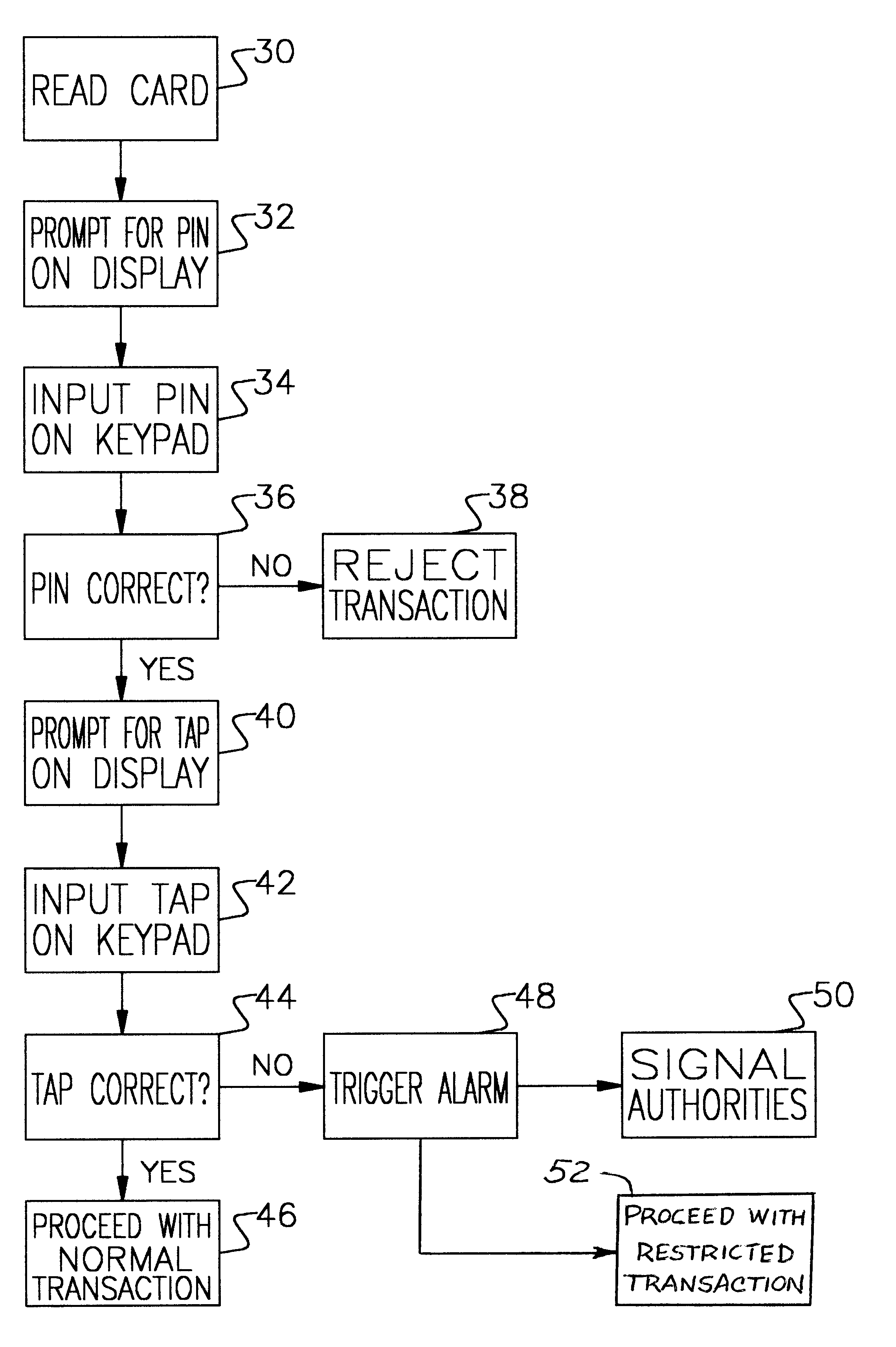
Briefly these and other objects of the present invention are accomplished by a computerized password verification system and associated method for discreet recognition and reporting of a duress transaction being imposed upon a user at an ATM or other remote cash-dispensing terminal. The inventive system utilizes conventional ATM hardware including a card reader, keypad and display screen together with its associated operating and communications software required for transaction processing, and further comprises the programmed generation and display of a list of transaction acceptance passwords (TAPs) with a prompt to the user for a TAP selection to confirm the validity of the immediate transaction. The prompted display of the TAP list appears following the initial acceptance of the user's personal identification number (PIN) and requires the ATM user to select the TAP from the list that is currently registered to the user. While selection of the user's current TAP from the prompted list verifies the immediate transaction, the selection of any other TAP from the displayed list would constitute a “panic” TAP that triggers the generation of a silent alert signal to the authorities. The generation and prompted display of the group list of TAPs from which the user can select one, without necessity of recalling a precise distress code, significantly increases the likelihood of the successful and discreet trigger of the alert signal by the ATM user under stress.

Problems solved by technology

These prior art security measures, generally complex and sophisticated in their designs, have been generally effective in disrupting and preventing electronic fraud in the normal transaction processing of ATMs.
They have not, however, effectively dealt with the common and ongoing problem of a duress transaction that is imposed upon an ATM user under threat of physical harm by a thief at a remote terminal location.
Typically in these duress transactions, the victimized ATM user is accosted by the thief and forced to make a cash withdrawal from the user's account.
Failure by the ATM user to follow a course other than the standard protocol, whether caused by panic confusion or done deliberately to reject the transaction and deny the withdrawal, will likely place the ATM user in immediate danger of retaliation.
Under the dramatic stress of the situation, it is quite likely that the panicked ATM user could go blank and not remember any part or variation of the assigned number and the resultant rejection of the transaction would place the innocent ATM user at a high risk of harm.

Method used


Image

  • Computerized password verification system and method for ATM transactions
  • Computerized password verification system and method for ATM transactions
  • Computerized password verification system and method for ATM transactions

Examples


Embodiment Construction

The following is a detailed description of the preferred embodiment of the present invention and the best presently contemplated mode of its production and practice. This description is further made for the purpose of illustrating the general principles of the invention but should not be taken in a limiting sense, the scope of the invention being best determined by reference to the appended claims.

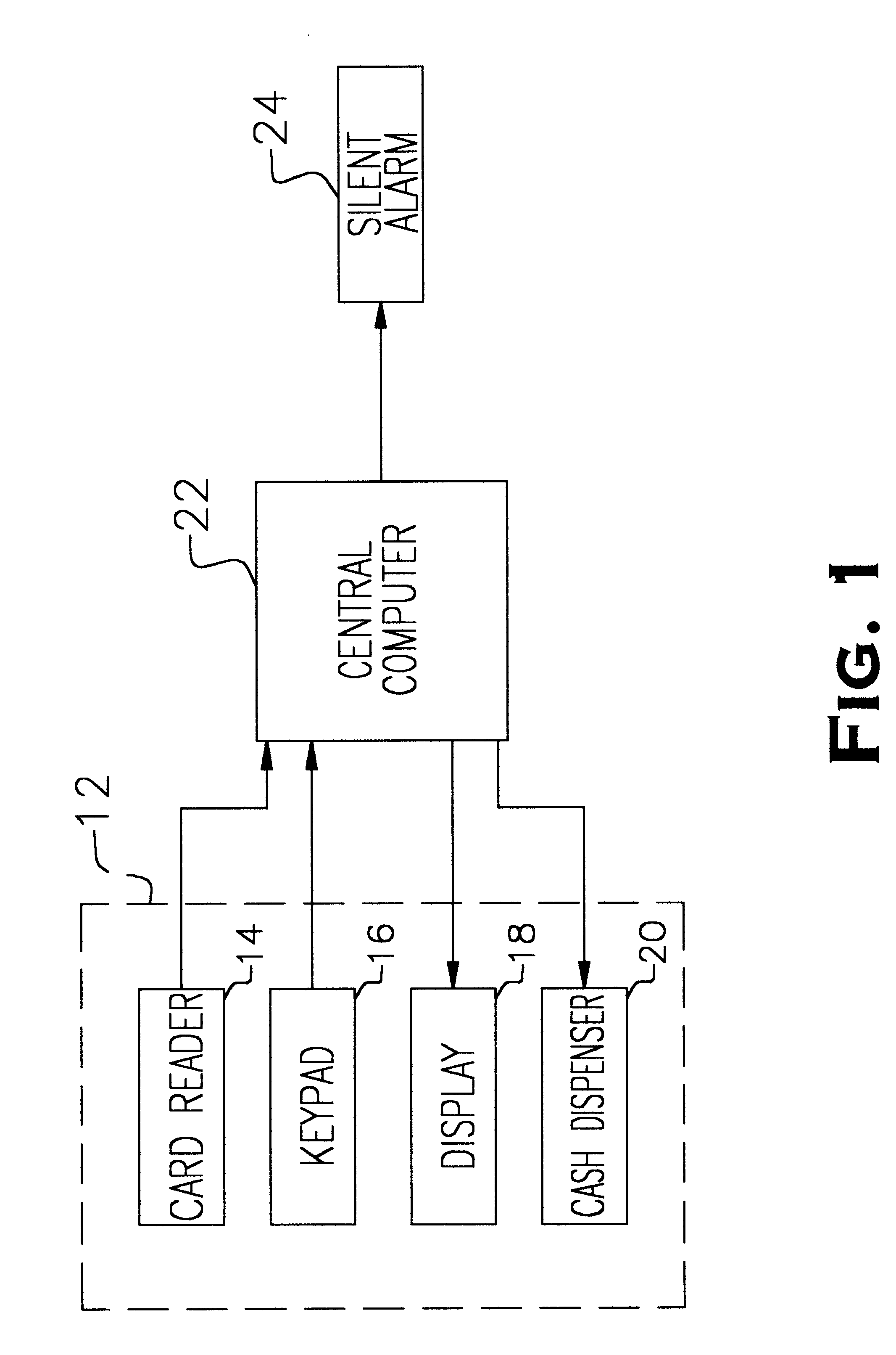
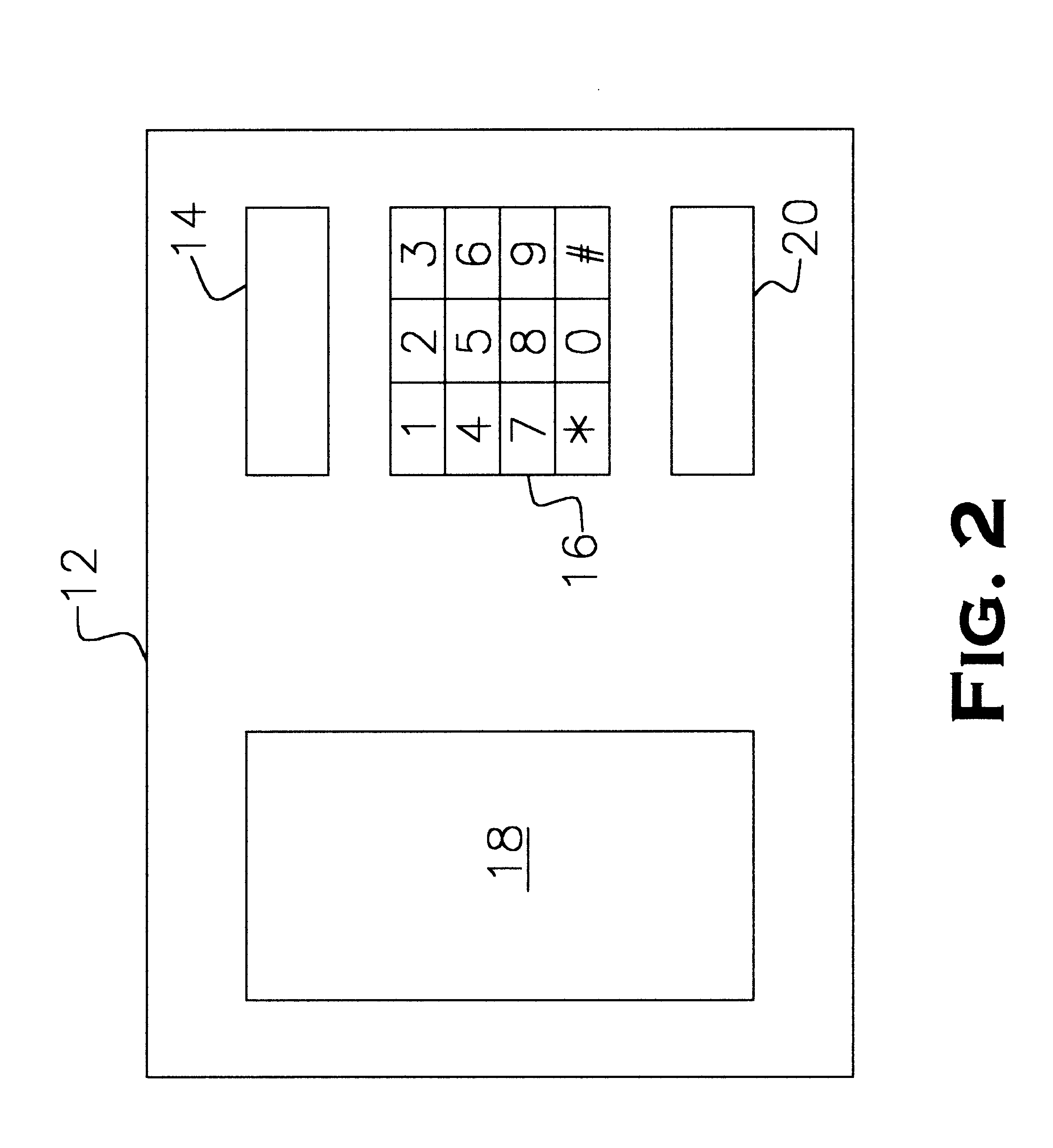
Referring now to FIGS. 1 and 2, the present password verification system incorporates and includes a standard automatic teller machine (ATM) 12 having a conventional magnetic card reader 14, a user keypad 16, a display screen 18 and a cash dispenser 20. A typical physical layout of these hardware features of the ATM 12 is shown for example in FIG. 2 but may be varied without affecting the system operation. The system also includes a central computer 22 that processes data obtained from the card reader 14 and that information entered by the user on keypad 16, and prompts the user via the di...


PUM


Abstract

A computerized password verification system and associated method is disclosed for discreet recognition and reporting of a duress transaction being imposed upon a user at an ATM or other remote cash-dispensing terminal. The inventive system utilizes conventional ATM hardware including a card reader, keypad and display together with its associated operating and communications software required for transaction processing, and further comprises the programmed generation and display screen of a list of transaction acceptance passwords (TAPs) with a prompt to the user for a TAP selection to confirm the validity of the immediate transaction. The prompted display of the TAP list appears following the initial acceptance of the user's personal identification number (PIN) and requires the ATM user to select the TAP from the list that is currently registered to the user. While selection of the user's current TAP from the prompted list verifies the immediate transaction, the selection of any other TAP from the displayed list would constitute a “panic” TAP that triggers the generation of a silent alert signal to the authorities.

Description

BACKGROUND OF THE INVENTIONThe present invention relates to computerized financial transactions of the type conducted at remote terminals, such as automatic teller machines (ATMs), and more particularly to a computerized system and associated method for password verification in the processing of a remote terminal transaction that improves the discreet recognition and reporting of a transaction imposed upon a user under duress.The recent proliferation of ATM installations throughout the United States has resulted in billions of ATM transactions being conducted annually. To protect ATMs against fraud and generally prevent unauthorized access to customer accounts by third parties using stolen or detected customer identification information, security systems have been devised for ATM use and incorporated within the associated electronic communications networks that encrypt and decrypt customer account information in transmissions between the ATM terminal and central computer in order to...

Claims


Application Information

Patent Timeline
Patent Type & Authority Patents(United States)
IPC IPC(8): G07F19/00G07F7/10
CPCG07F7/10G07F19/207G07F19/20
Inventor RUSSIKOFF, RONALD K.
Owner RUSSIKOFF RONALD K
Why Eureka
Try Eureka