Gradient calculating camera board

a camera board and gradient technology, applied in the field of image signal processing, can solve the problems of large amount of processing required, complicated video processing boards, and complicated processing equipment,

Inactive Publication Date: 2005-03-29
SNAP ON INC
View PDF43 Cites 55 Cited by
  • Summary
  • Abstract
  • Description
  • Claims
  • Application Information

AI Technical Summary

Benefits of technology

Yet a further improvement in the image sensing module involves optically isolating the strobe circuit. The module typically comprises an image sensor circuit, an electronic strobe circuit, a controller circuit coupled to the image sensor circuit and the electronic strobe circuit, and a communication interface circuit. At least one optical isolator is coupled to the electronic strobe circuit, for optically isolating the strobe circuit from the other circuits of the image sensing module. The optical isolation of the strobe circuit from the other circuits prevents the power from the strobe circuit feeding back into the logic circuits and damaging the logic circuits.

Problems solved by technology

In current machine vision systems, such as the 3D aligners, there are two general ways to process the video image signals from the cameras, both of which have limitations or problems.
However, video processing boards often require use of complex, expensive processors to perform all of the necessary calculations required for the image algorithms.
However, the amount of processing required is quite large and imposes a substantial burden on the central processing unit of the host computer.
Such intense processing may unacceptably slow down operation of the host computer.
If the particular machine vision application requires processing of images from multiple cameras, the amount of the data to be handled and the attendant number of necessary calculations may overwhelm the host computer.

Method used


Image

  • Gradient calculating camera board
  • Gradient calculating camera board
  • Gradient calculating camera board

Examples


Embodiment Construction

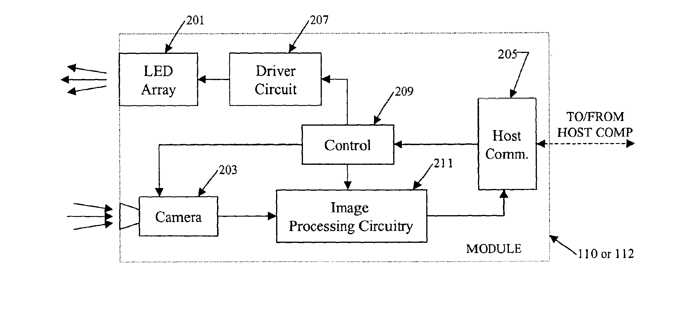
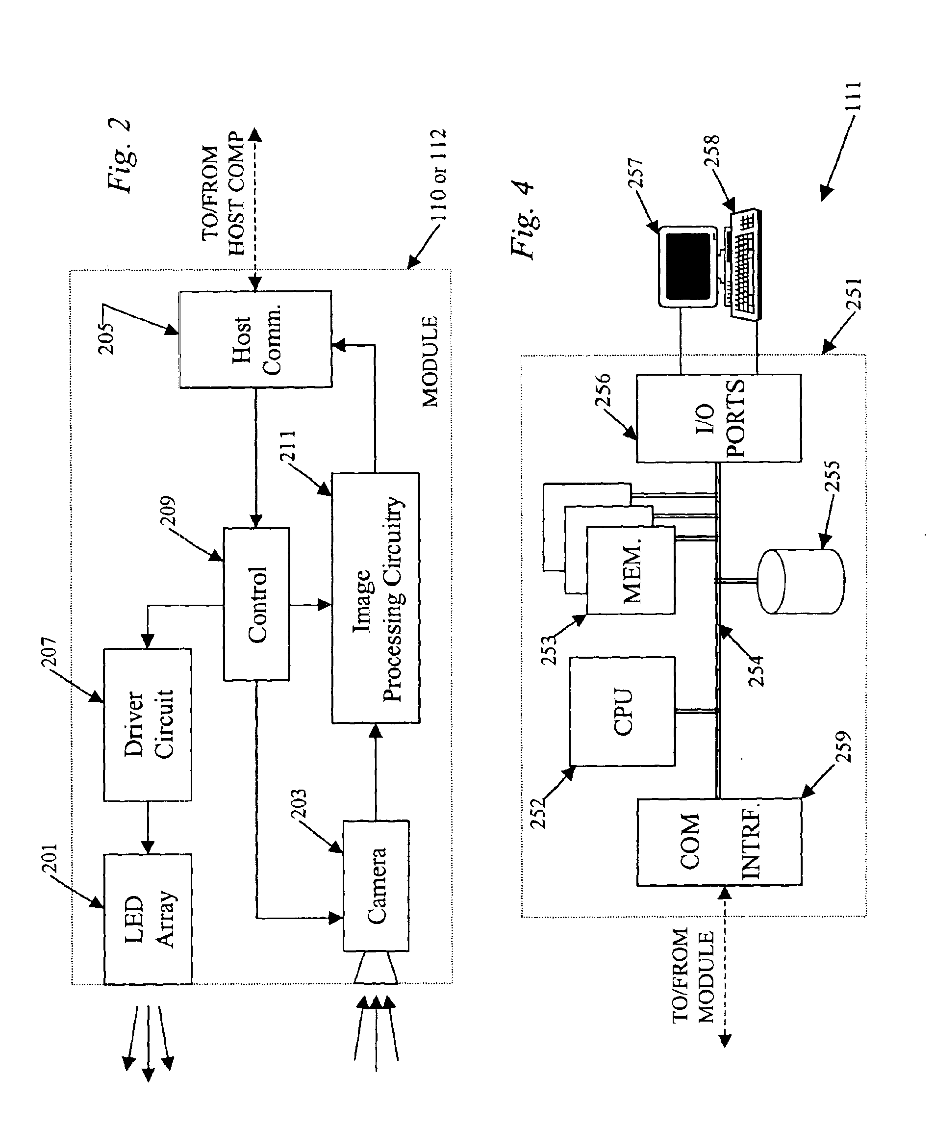
The various examples disclosed herein relate to systems and techniques for implementing machine vision in an enhanced manner by providing an imaging module having an image sensor as well as associated pre-processing circuitry. In the examples, the pre-processing circuitry in the imaging module a background subtraction and / or a gradient calculation. The pre-processing circuitry or other means in the imaging module may also provide data compression for reduced bandwidth communication to a host processor. Reference now is made in detail to the examples illustrated in the accompanying drawings.

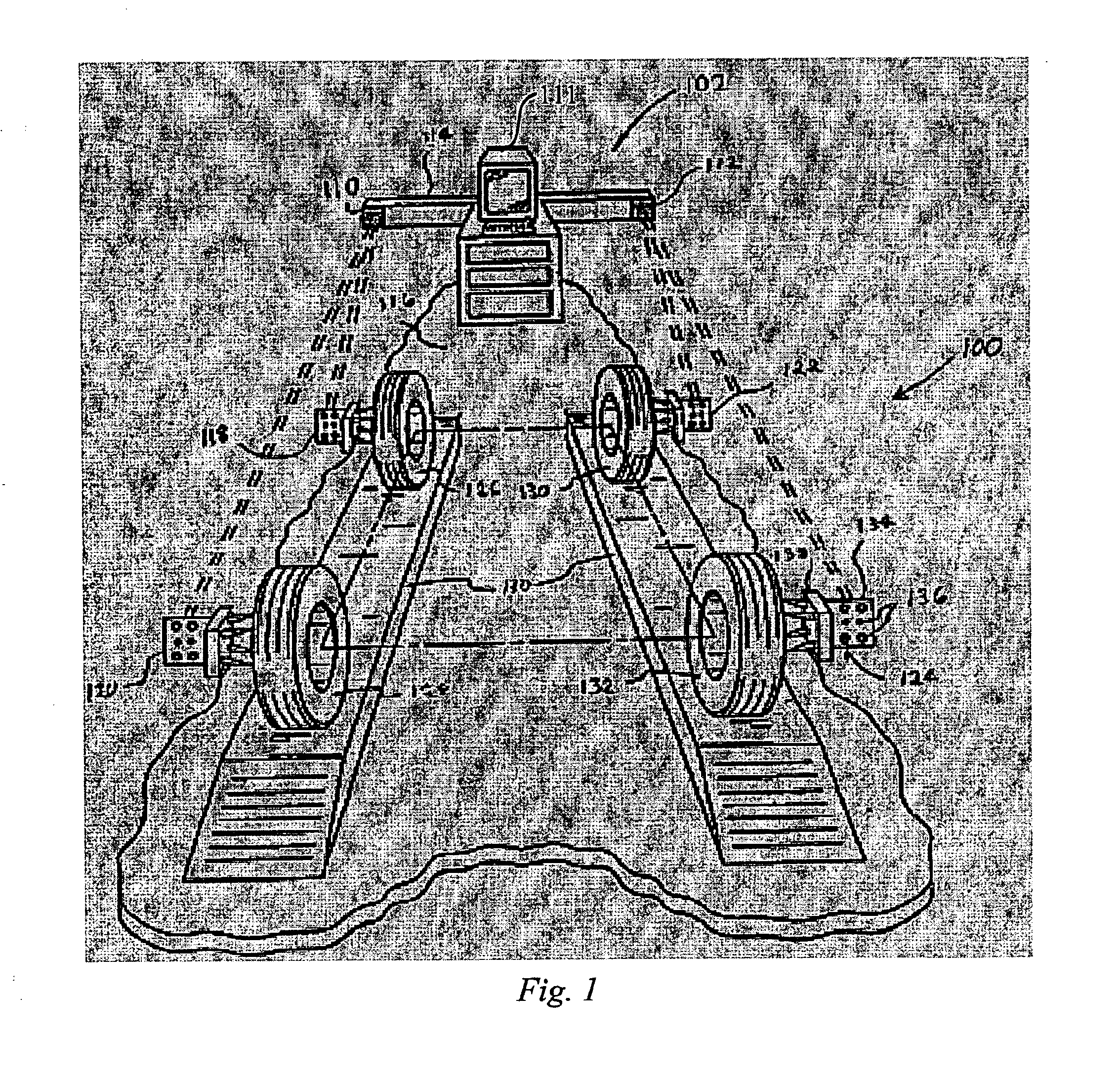
The concepts discussed herein are applicable in a variety of different types of machine vision systems. For purposes of discussion, it may be helpful to consider a specific example of a machine vision system, such as a 3D aligner as illustrated in FIG. 1, before going into the details of the imaging module.

In the example shown, the aligner system 100 consists of three major components. The first o...


PUM


Abstract

In a machine vision system utilizing computer processing of image data, an imaging module incorporates the image sensor as well as pre-processing circuitry, for example, for performing a background subtraction and/or a gradient calculation. The pre-processing circuitry may also compress the image information. The host computer receives the pre-processed image data and performs all other calculations necessary to complete the machine vision application, for example, to determine one or more wheel alignment parameters of a subject vehicle. In a disclosed example useful for wheel alignment, the module also includes illumination elements, and the module circuitry provides associated camera control. The background subtraction, gradient calculation and associated compression require simpler, less expensive circuitry than for typical image pre-processing boards. Yet, the pre-processing at the imaging module substantially reduces the processing burden on the host computer when compared to machine vision implementations using direct streaming of image data to the host computer.

Description

TECHNICAL FIELDThe present subject matter relates to a technique for processing image signals for input to a computer or the like, for machine vision and similar applications, which utilizes a gradient calculation and / or a background subtraction.BACKGROUNDAn increasing variety of industrial applications involve machine vision measurements taken by processing image data from cameras. For example, wheels of motor vehicles may be aligned on an alignment rack using a computer-aided, three-dimensional (3D) machine vision alignment apparatus. In such a technique, one or more cameras of the alignment apparatus view targets attached to the wheels of the vehicle. The cameras form images of the targets, and a computer in the alignment apparatus analyzes the images of the targets to determine wheel position. The computer guides an operator in properly adjusting the wheels to accomplish precise alignment, based on calculations obtained from processing of the image data.Examples of methods and a...

Claims


Application Information

Patent Timeline
Patent Type & Authority Patents(United States)
IPC IPC(8): G06T7/00
CPCG06T7/004G06T7/70G01B11/2755G01B2210/26
Inventor ROBB, MICHAEL J.GLICKMAN, STEVE L.O'MAHONY, PATRICK BRENDANGURURAJ, MANJULAJACKSON, DAVID A.GILL, GEORGE M.BRYAN, ERIC F.
Owner SNAP ON INC
Why Eureka
Try Eureka