Polymer shrinkage tensometer

Inactive Publication Date: 2005-03-29
ADA FOUND
View PDF3 Cites 5 Cited by
  • Summary
  • Abstract
  • Description
  • Claims
  • Application Information

AI Technical Summary

Benefits of technology

The present invention overcomes the limitations discussed with respect to prior efforts by providing an apparatus and method that can be readily adapted to simulate the stress/strain conditions of various cavity preparations and sizes. The apparatus and method provide for rapidly and reproducibly establishing a wide range of C-factors, and controlling environmental test conditions such as temperature, light, and water so

Problems solved by technology

Movement between the cantilever beam and the reference base resu

Method used


Image

  • Polymer shrinkage tensometer
  • Polymer shrinkage tensometer
  • Polymer shrinkage tensometer

Examples


example 1

The first test example involved curing a commercially available dental composite (TPH®, Dentsply International) by curing the sample for 240 seconds using a dental curing light for curing activation. The test sample was 4 mm in diameter and 4.0 mm thick, simulating the approximate side and bonded surface area of a typical three surface dental filling on a bicuspid tooth.

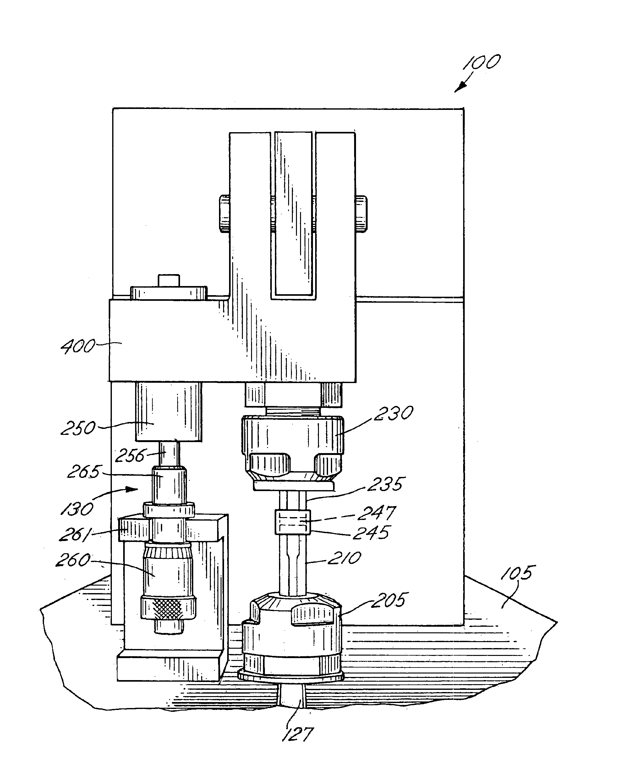
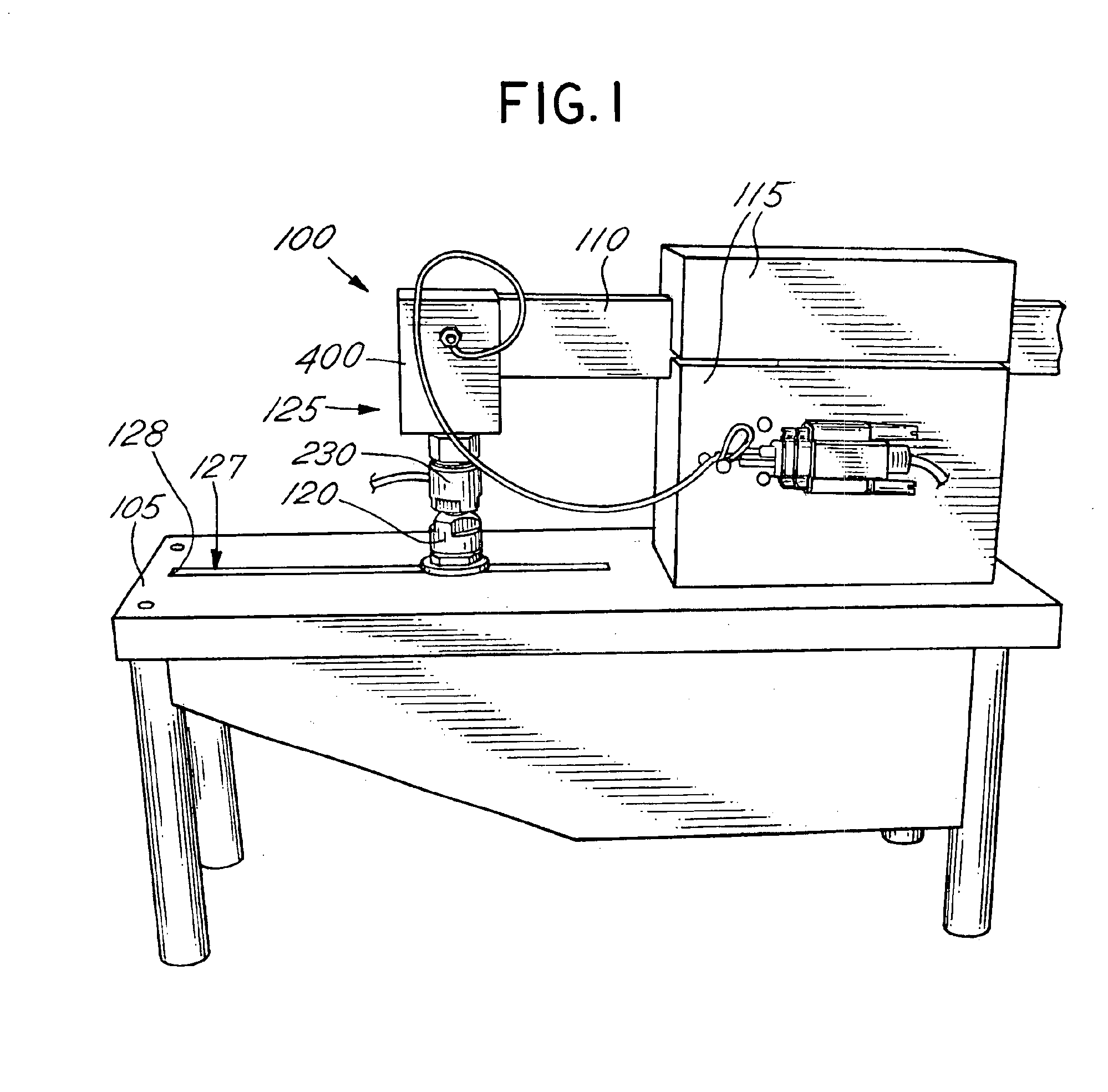
For set-up of the tensometer 100, the cantilever portion of the beam member 110 was set to 12.65 cm, which resulted in a maximum beam flexure of approximately 20 micrometers during curing. This displacement was chosen as mid-range from values reported in several clinical studies of cuspal deflection during curing of similar restorations.

The tensometer 100 was further configured using two 4 mm diameter quartz rods for the upper and lower rods 235, 210. The end faces of the quartz rods were polished and treated with two coats of a silane coupling agent to enhance polymer adhesion. The rods were inserted into the collet...

example 2

The operator repeated the experiment of example 1, changing only the sample length (i.e., the gap between the quartz rods) to be 0.5 mm. This change in sample length resulted in a C-factor 8 times greater than that for example 1. FIG. 13 illustrates the results for four tests run under this new C-factor. Comparing the results from example 1 and example 2, the results indicate that longer samples with lower C-factors result in higher ultimate stress.

example 3

Lastly, the operator conducted a similar experiment using a different test material (P60®, 3M) and a sample length of 1 mm. The operator performed one test run, resulting in the beam deflection plot 990, shown in FIG. 14. The operator configured the test apparatus to calculate the compliance of various tensometer 100 components. For example, the load, area, length and modulus values for the quartz (glass) rods were used to determine the elongation 991, under stress, of the rods. The composite sample elongation 992 was similarly calculated. Combining the measured beam deflection 990 and the calculated rod stretch 991 and the composite shrinkage 992 results in the total sample shrinkage 993. The test results were found to be close to the expected shrinkage for the particular composite.


PUM


Abstract

An apparatus and method for measuring the characteristics of curing polymers. The apparatus and method utilize cantilever beam technology to determine characteristics of polymers during the curing process, including but not limited to, stress-related forces that develop during the polymer curing process. The apparatus and method also provide for controlling and monitoring environmental conditions during the curing process.

Description

STATEMENT REGARDING FEDERALLY SPONSORED RESEARCH OR DEVELOPMENT(Not applicable)FIELD OF THE INVENTIONThis invention relates generally to the measurement of characteristics of curing polymers. More particularly, this invention relates to the measurement of stress-related forces and displacements that develop during the polymer curing process, for example during the curing of dental polymer material.BACKGROUND OF THE INVENTIONPolymerization shrinkage is one of the major deficiencies in dental polymers. Public and private research groups are expending considerable effort to develop materials and methods to reduce this shrinkage. The researchers require accurate, reproducible and pertinent measurements of shrinkage properties to assess the effectiveness of their developments. Researchers have developed several methods to assess the stress developed by dental filling composites as they shrink, but none of these previously developed methods have the ability to rapidly and accurately track...

Claims


Application Information

Patent Timeline
IPC IPC(8): A61K6/00G01N3/08G01N3/00
CPCA61K6/00G01N3/08G01N2203/0092G01N2203/0033G01N2203/0016
Inventor EICHMILLER, FREDERICK C.
Owner ADA FOUND
Why Eureka
Try Eureka