Master cylinder for a brake or clutch of a motorcycle or bike

a technology of master cylinder and brake or clutch, which is applied in the direction of brake action initiation, coupling, braking system, etc., can solve the problems of insufficient satisfaction of other requirements, inability to achieve the desirable strength of the cylinder and the structure with respect to working stress and knocks, and difficulty in repairs, etc., to achieve good stiffness and the ability to withstand working stresses, and the effect of low cos

Inactive Publication Date: 2005-03-29
FRENI BREMBO SPA
View PDF6 Cites 36 Cited by
  • Summary
  • Abstract
  • Description
  • Claims
  • Application Information

AI Technical Summary

Benefits of technology

The disadvantages of the prior art are overcome and all of the requirements desirable for a motorcycle or bicycle brake are achieved by the brake (or clutch) master cylinder of the present invention in which the cylinder body is produced by moulding of plastics material reinforced with glass fibre, without constructional complications, without the need for machining operations, and without the need for auxiliary elements for connection to the hydraulic circuit, or for metal inserts.
The cylinder body also incorporates a hydraulic-fluid reservoir the walls of which strengthen the structure of the body and provide a rigid frame for the anchorage of two support lugs of the articulation pin of the operating lever and for a seat for fixing to the handlebar of the vehicle.
A strong and compact structure which takes up little space, which has good stiffness and ability to withstand working stresses and which, at the same time, is relatively resilient and able to absorb stresses resulting from possible knocks is thus produced, in combination with considerable ease of installation, of setting-up of the hydraulic system, and of repair if necessary, and with an extremely low cost.

Problems solved by technology

A structure which is light, relatively inexpensive, and resistant to atmospheric agents is thus produced, but the other requirements are not adequately satisfied.
In particular, the desirable strength of the cylinder and of the structure with respect to working stresses and to knocks is not achieved.
Moreover, any repairs are difficult because they involve the risk of loss of hydraulic fluid.
All of this is detrimental to cost and to ease of installation, setting-up, and repair, if necessary.

Method used


Image

  • Master cylinder for a brake or clutch of a motorcycle or bike
  • Master cylinder for a brake or clutch of a motorcycle or bike
  • Master cylinder for a brake or clutch of a motorcycle or bike

Examples


Embodiment Construction

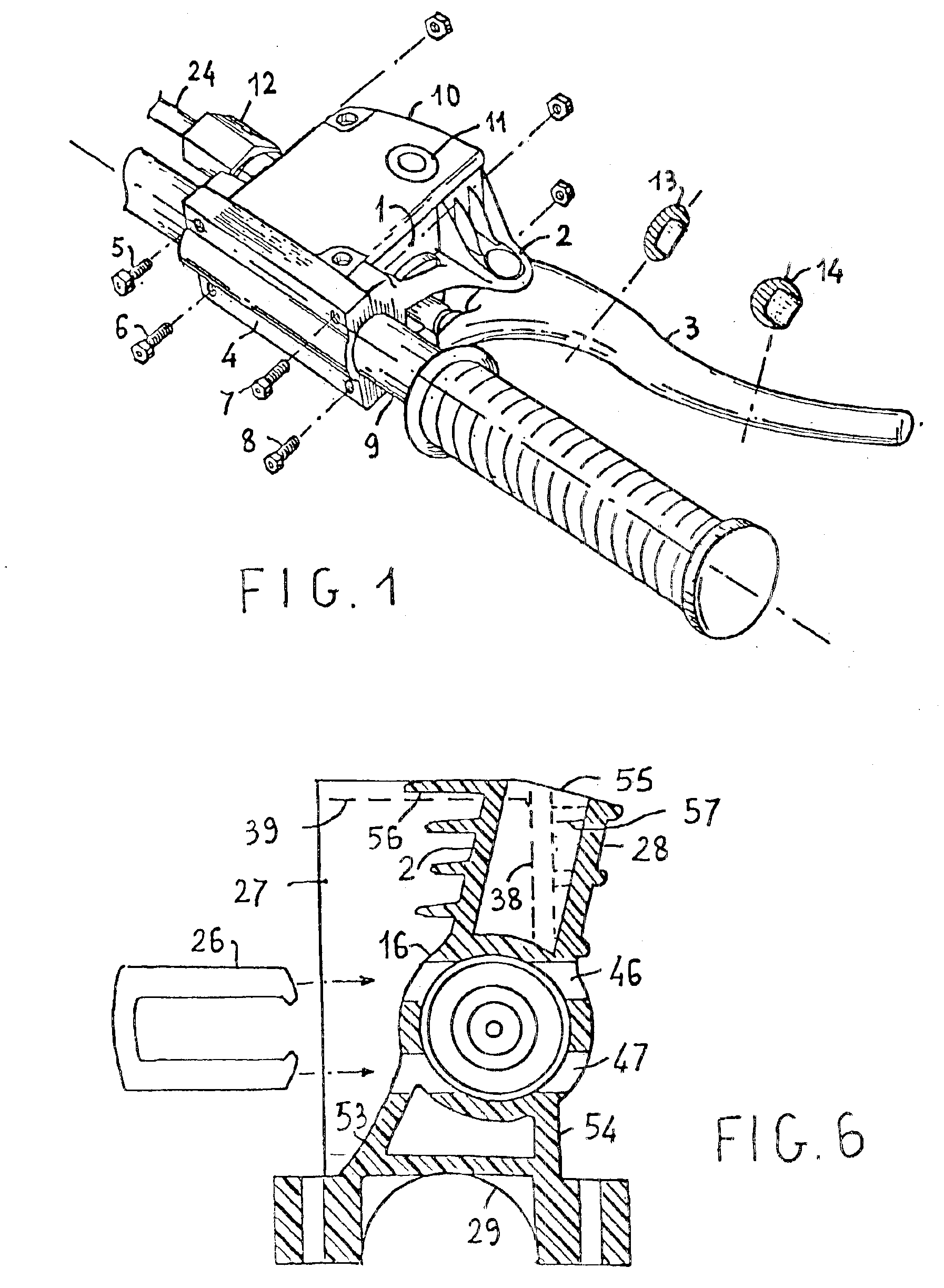
FIG. 1 is an overall perspective view of a preferred embodiment of the motorcycle brake or clutch master cylinder unit fitted on a motorcycle handlebar.

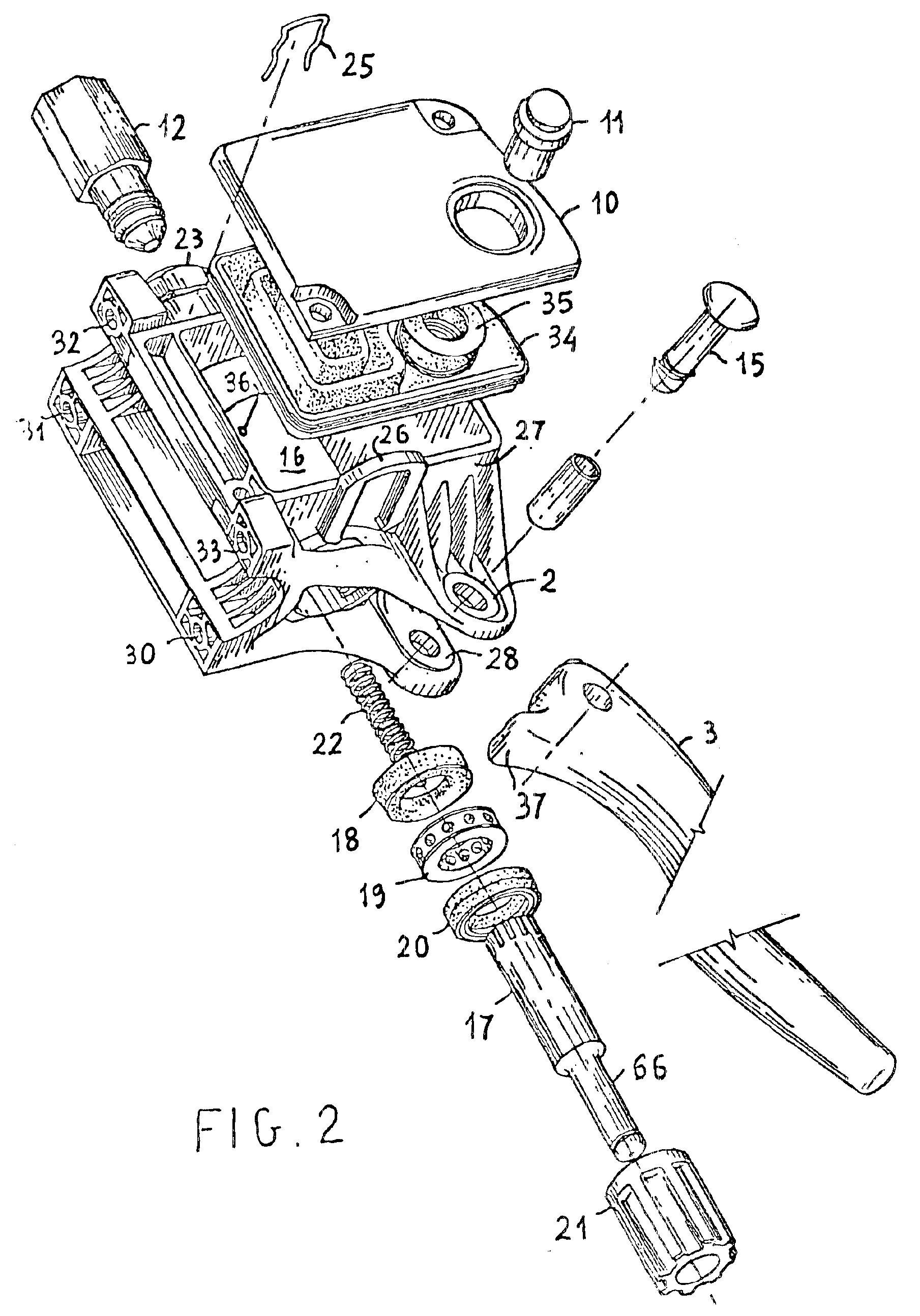
The unit comprises a body 1 having a pair of lugs, of which only one, indicated 2, is visible in the drawing, and between which an operating lever or handle 3 is articulated, the body 1 also having a fixing seat connected, by means of fixing screws 5, 6, 7, 8, (which have respective nuts, or are even self-tapping screws), to a complementary seat 4 in order to fix the unit to the handlebar 9.

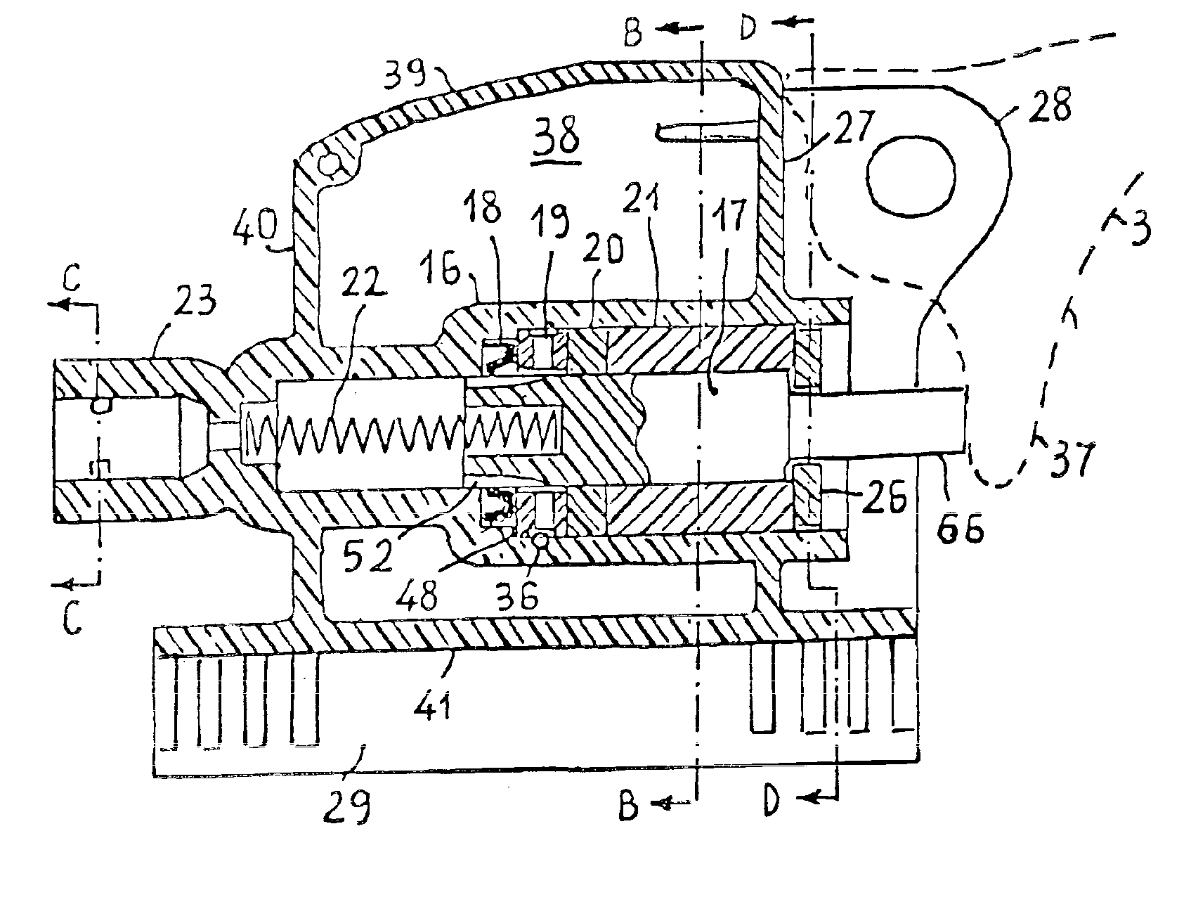
The cylinder of the master cylinder unit (in which the piston and its sealing members are housed) is formed inside the body 1 and the body 1 at the same time forms a hydraulic-fluid reservoir which is in communication with the interior of the cylinder and is closed by a removable lid 10 with a plug / window 11 for checking the hydraulic-fluid level and possibly topping it up.

The body also has a hydraulic outlet constituted by a cylindrical housing w...


PUM


Abstract

A brake / clutch master cylinder for a motorcycle / bicycle or the like, with a body which is produced by moulding of plastics material reinforced by glass fibre without the need for machining operations or metal inserts and which forms, together with the cylindrical shell of the master cylinder, a hydraulic-fluid reservoir, a coupling sleeve for a male quick-fit hydraulic connector, and a seat for fixing to a handlebar, the body having a high degree of structural stiffness with respect to working stresses and adequate resilience for impact stresses imparted to the body by means of the hand operating lever.

Description

FIELD OF THE INVENTIONThe present invention relates to a brake or clutch master cylinder to be mounted on the handlebars of a motorcycle, bicycle, or the like.BACKGROUND OF THE INVENTIONIt is known that hydraulic braking systems are being used ever more widely in light vehicles such as motorcycles and bicycles.For these vehicles, the control or master actuator has to satisfy various requirements including: low cost, light weight, resistance to atmospheric agents, impact strength and an ability to withstand high working stresses, ease of installation on and removal from the vehicle, ease of connection to the braking system, as well as ease of replacement of the mechanical hand-operating element constituted by the hand lever which is most exposed to knocks and to the risk of breakage that does not prejudice the functionality of the other parts of the braking system.STATE OF THE ARTIn order to satisfy at least some of these requirements, it has been proposed, as described in U.S. Pat. ...

Claims


Application Information

Patent Timeline
Patent Type & Authority Patents(United States)
IPC IPC(8): B60T11/22B62L3/00B60T17/04B60T11/16B60T17/00B62L3/02F16D25/08
CPCB60T11/22B62L3/023B60T17/043
Inventor HUSTER, MICHAELSTUHLER, ANDREABONFANTI, ROBERTO
Owner FRENI BREMBO SPA
Why Eureka
Try Eureka