Hand tool apparatus for orbital drilling

a technology of orbital drilling and hand tools, which is applied in the direction of turning apparatus, driving apparatus, large fixed members, etc., can solve the problems of reducing the practicality of the disclosed hand tool, and imposing the geometry of the cutting tool. , to achieve the effect of reducing the overhang of the tool, reducing the bending, and reducing the moment of the cutting tool

Inactive Publication Date: 2005-03-29
NOVATOR
View PDF40 Cites 31 Cited by
  • Summary
  • Abstract
  • Description
  • Claims
  • Application Information

AI Technical Summary

Benefits of technology

An advantage of the present invention is that the hand tool is more lightweight and compact than the previous devices.
Another advantage is that the tool overhang is minimized, thereby reducing the bending, moment on the cut

Problems solved by technology

The requirements imposed on the geometry of the cutting tool are not particularly high, on the other hand, since every individual tool is simply calibrated before use.
Although this aforementioned disclosure outlines some principles, the disclosed hand tool does not offer a feasible and practical solution.
One obvious limitation is that the disclosed concepts do not present a s

Method used


Image

  • Hand tool apparatus for orbital drilling
  • Hand tool apparatus for orbital drilling
  • Hand tool apparatus for orbital drilling

Examples


Embodiment Construction

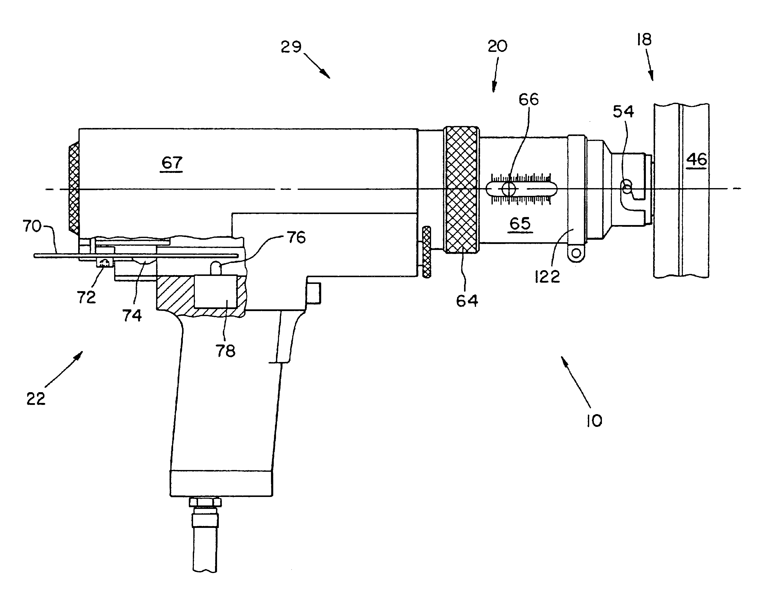
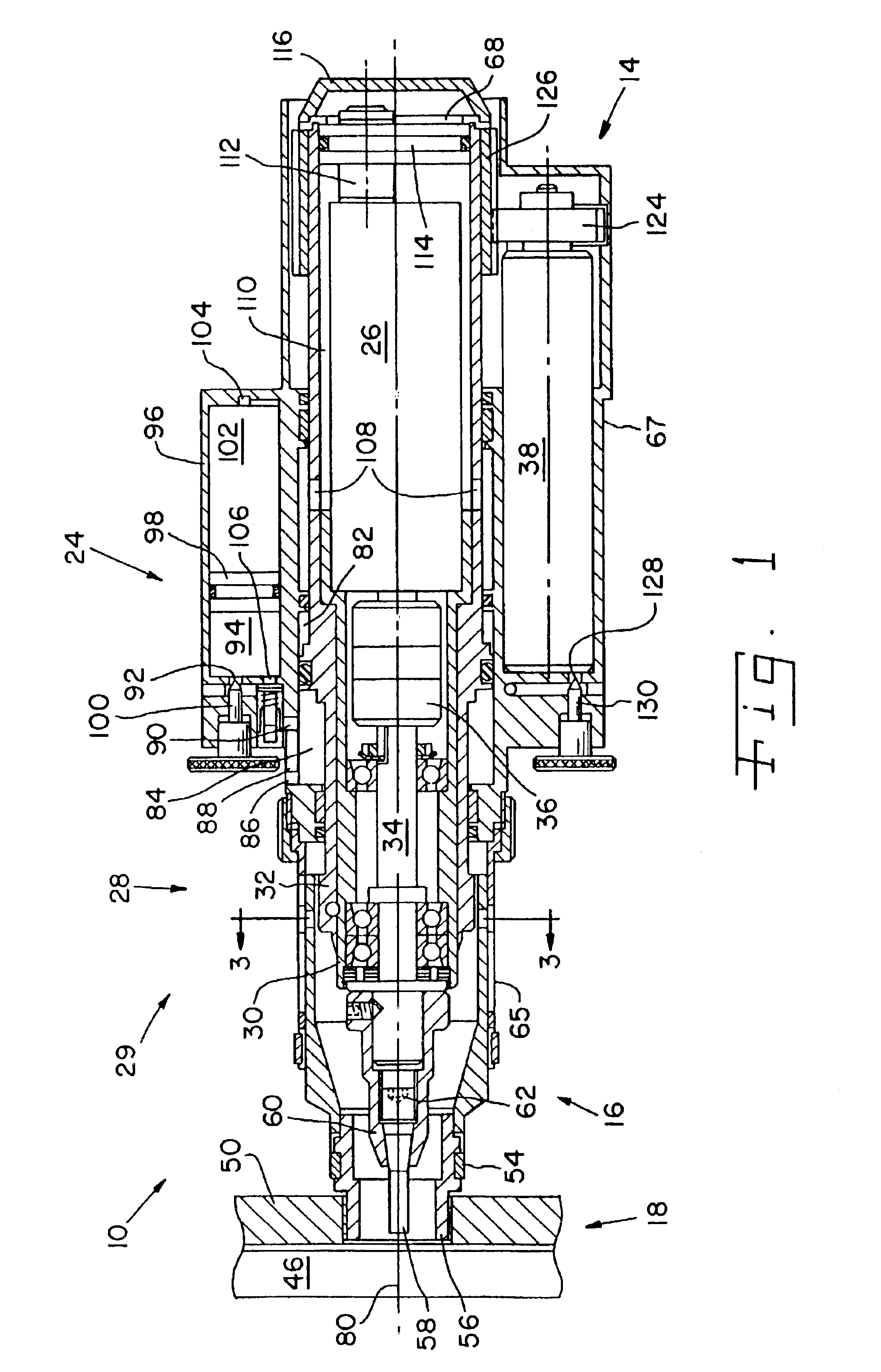
Referring now to the drawings and particularly to FIG. 1, there is shown a hand tool apparatus in the form of a pneumatic portable drill 10 including an actuating assembly 12, eccentric rotation mechanism 14, tool assembly 16, template assembly 18, axial positioning mechanism 20 (FIG. 6), and stroke adjustment mechanism 22.

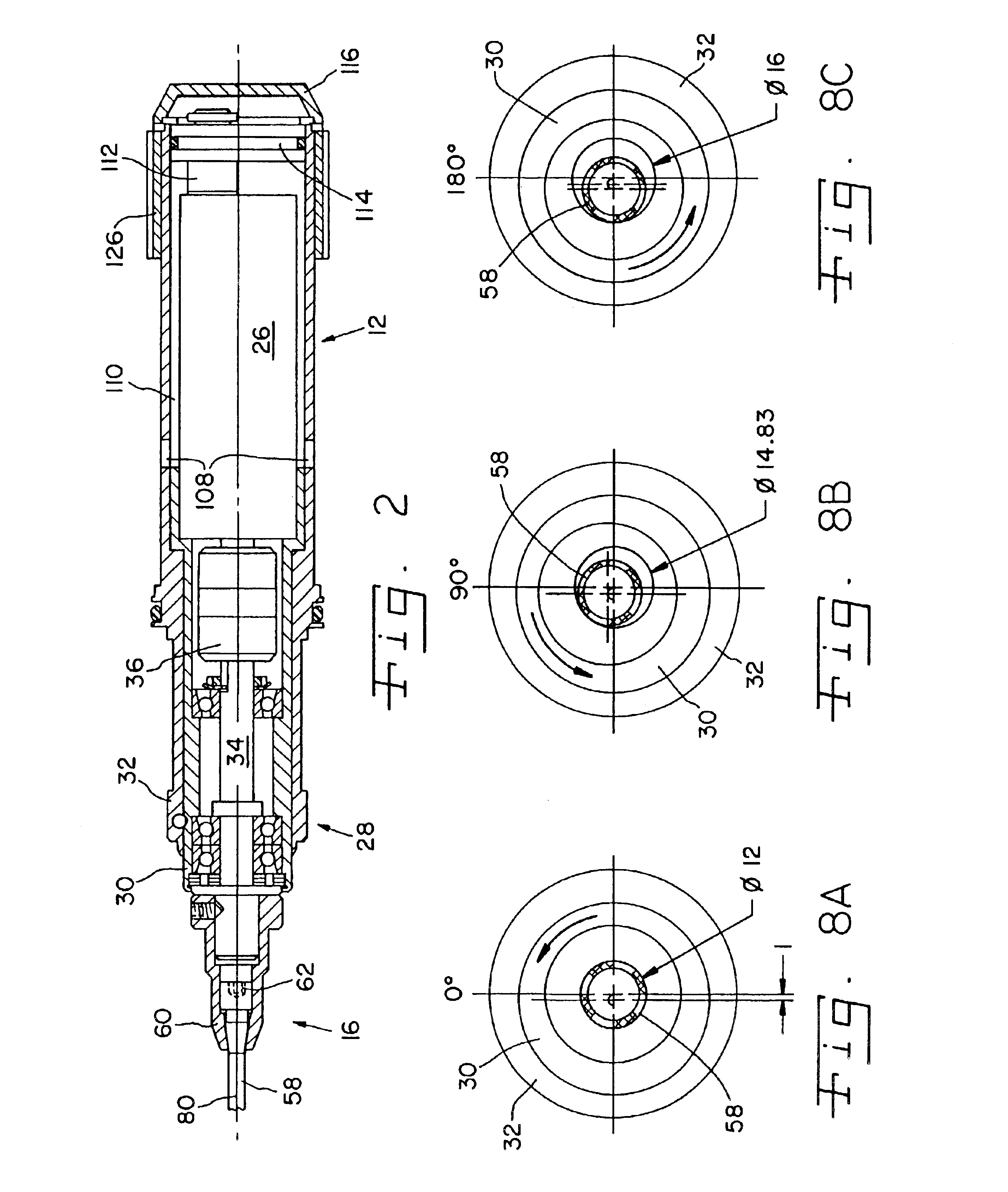
Actuating assembly 12 includes an axial feed mechanism 24, a spindle motor 26, and a radial offset mechanism 28 (FIG. 3), all contained within a single housing 29. Radial offset mechanism 28 includes a concentric cylindrical inner sleeve 30 positioned in a concentric cylindrical outer sleeve 32. Inner sleeve 30 and outer sleeve 32 are rotatable relative to each other. An axle or shaft 34 of spindle motor 26 extends through a clutch 36 and is rotatably mounted in inner sleeve 30.

Eccentric rotation mechanism 14 includes a motor 38 for rotating actuating assembly 12 and thereby tool assembly 16 about a principal axis 40.

Template assembly 18 includes a sleeve 42 (FIG....


PUM


Abstract

A hand tool apparatus uses a cutting tool with a first width and a tool axis to machine a hole in an object. The hole has a second width at least as large as the first width of the cutting tool. The tool axis passes through a predetermined point on a surface of the object. The apparatus includes an actuating assembly including a housing. The housing contains an axial feed mechanism configured for moving the cutting tool in an axial direction, a spindle motor configured for rotating the cutting tool about the tool axis, and a radial offset mechanism. The radial offset mechanism is configured for moving the axial feed mechanism in a radial direction such that the tool axis is offset from a principal axis. A motor is configured for rotating said axial feed mechanism and the cutting tool about the principal axis.

Description

BACKGROUND OF THE INVENTION1. Field of the InventionThe present invention relates to a hand tool for cutting a hole in an object, and, more particularly, a hand tool for cutting a hole that has a larger diameter than the diameter of the cutting tool.2. Description of the Related ArtU.S. Pat. No. 5,641,252 discloses a method for machining holes in a fiber reinforced composite material by using at least one cutting tool with wear resistant surface positioned eccentrically in relation to a central axis. The material is machined simultaneously in both an axial and a radial direction by causing the tool to move axially while rotating not only about its own axis, but also eccentrically about the central axis. In accordance with one particular characterizing feature of the invention, the workpiece is oriented in such a way that the axis of rotation of the tool is essentially orthogonal in relation to the longitudinal directions of the fibers in the immediate vicinity of the point where the...

Claims


Application Information

Patent Timeline
IPC IPC(8): B23Q5/00B23Q5/04B23B49/00B23B49/02B23C3/00B23C3/34B26F1/16B23B35/00B23B45/14
CPCB23B35/00B23C3/02B23Q5/046B23B49/023Y10T409/307616B23B2260/088B23C2220/52Y10T409/3084Y10T408/675Y10T408/56245Y10T408/566Y10T409/306216Y10T408/6757Y10T408/99Y10T82/125Y10T409/306384Y10T409/304424Y10T409/306776Y10T409/308624Y10T408/5623Y10T409/307112Y10T408/18
Inventor LINDERHOLM, DAG G.
Owner NOVATOR
Why Eureka
Try Eureka