Adhesive microstructure and method of forming same

a microstructure and adhesive technology, applied in the field of adhesive microstructure and adhesive forming method, can solve the problems of unexplored or fully understood adhesive mechanisms in nature, and achieve the effect of improving adhesion to rough surfaces and being easy to disengag

Inactive Publication Date: 2005-03-29
RGT UNIV OF CALIFORNIA
View PDF17 Cites 249 Cited by
  • Summary
  • Abstract
  • Description
  • Claims
  • Application Information

AI Technical Summary

Benefits of technology

Certain embodiments of the invention can include one or more of the following advantages. A fabricated microstructure provides improved adhesion to rough surfaces, while being rel

Problems solved by technology

Adhesive mechanisms in nature have been studied,

Method used


Image

  • Adhesive microstructure and method of forming same
  • Adhesive microstructure and method of forming same
  • Adhesive microstructure and method of forming same

Examples


Embodiment Construction

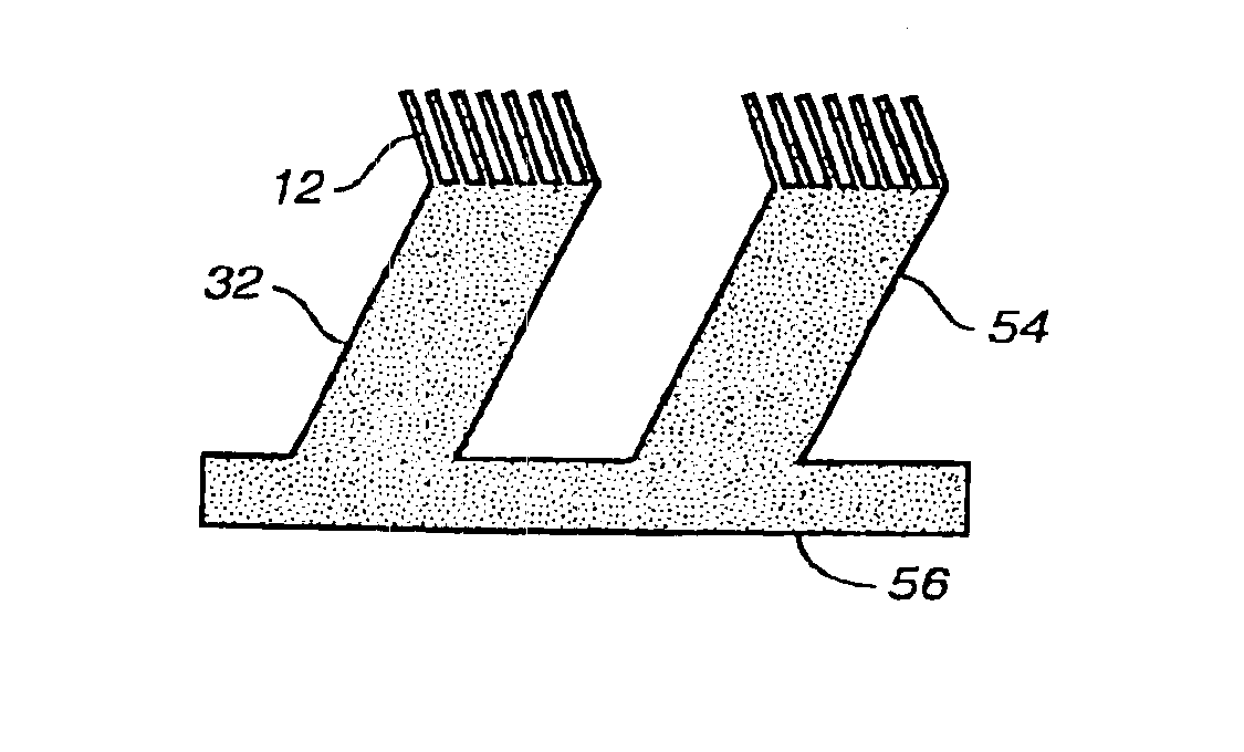
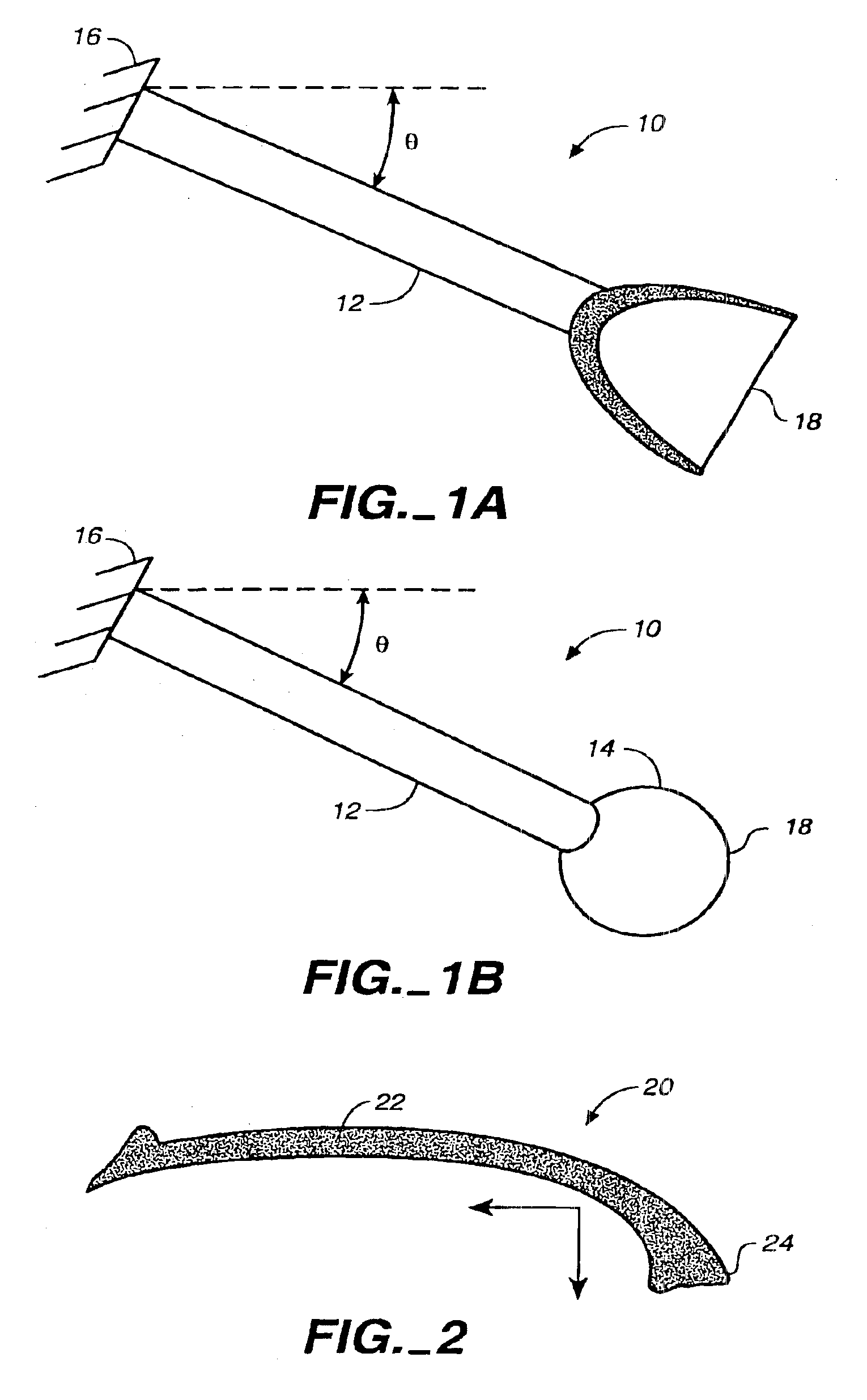
The invention is directed toward the use of microfabricated structures to achieve adhesion. In particular, the invention uses a fabricated seta-like structure. As shown in FIGS. 1A and 1B, a seta-like structure 10 includes a stalk 12. Positioned at an end of the member or stalk 12 is a spatula or protrusion 14. An array of spatulae or protrusions may also be located at the end of the stalk. The stalk supports the spatula, or an array of spatulae, at an oblique angle (neither perpendicular nor parallel) relative to a supporting surface 16. This angle may be between about 15 and 75 degrees (°), and more preferably between about 30° and 60°. This angle, in one embodiment, is 30°.

The supporting surface 16, for instance, may be a shaft or substrate. As shown in FIGS. 1A and 1B, the supporting surface 16 is a flexible or compliant substrate. This substrate may be made from such materials as polymers, for example, polyester, polyurethane and polyimide.

Ideally, each spatula 14 or each spatu...


PUM

PropertyMeasurementUnit
Angleaaaaaaaaaa
Angleaaaaaaaaaa
Angleaaaaaaaaaa

Abstract

A fabricated microstructure comprising at least one protrusion capable of providing an adhesive force at a surface of between about 60 and 2,000 nano-Newtons. A stalk supports the protrusion at an oblique angle relative to a supporting surface. The microstructure can adhere to different surfaces.

Description

BRIEF DESCRIPTION OF THE INVENTIONThis invention relates generally to the fabrication and use of micro- and nano-scale structures. More particularly, this invention relates to a fabricated adhesive microstructure.BACKGROUNDThere is an ongoing need for improved adhesives. Improved adhesives have applications ranging from everyday aspects of life (e.g., tape, fasteners, and toys) to high technology (e.g., removal of microscopic particles from semiconductor wafers, transporting fiber optic devices, and assembly of sub-mm mechanisms, particularly those including micro-fabricated components, or components that cannot tolerate regular grippers, adhesives, or vacuum manipulators).Adhesive mechanisms in nature have been studied, but have not been fully understood or exploited. For example, geckos are exceptional in their ability to rapidly climb up smooth vertical surfaces. The mechanism of adhesion used in geckos, Anolis lizards, some skinks, and some insects, has been debated for nearly a...

Claims


Application Information

Patent Timeline
IPC IPC(8): A44B18/00B29C33/42B81C1/00C09J7/00
CPCA44B18/0003A44B18/0061B29C33/42B81B3/0059C09J7/00F16B2/005F16B5/07B08B1/00B08B7/0028A44B18/0049Y10T428/24008B29L2031/756B81B2203/0361B82Y30/00C09J2201/626Y10S977/84Y10T24/2742Y10T428/24355Y10T428/2978Y10T428/24174Y10T24/27Y10T428/2976Y10T428/2913Y10T428/298Y10T428/28Y10T428/2973Y10T428/23943C09J2301/31
Inventor FEARING, RONALD S.SITTI, METIN
Owner RGT UNIV OF CALIFORNIA
Why Eureka
Try Eureka