Fault current limiter

a technology of fault current and limiter, which is applied in the direction of transformer/inductance magnetic core, continuously variable inductance/transformer, inductance, etc., can solve the problems of long power outage time, high cost of fused circuit breakers, and high cost of buying and maintaining circuit breakers

Inactive Publication Date: 2005-03-29
GENERAL ELECTRIC CO
View PDF22 Cites 16 Cited by
  • Summary
  • Abstract
  • Description
  • Claims
  • Application Information

AI Technical Summary

Problems solved by technology

Circuit breakers designed to withstand 200 kA short circuit currents are expensive.
Fused circuit breakers have several limitations in that fused circuit breakers need to be manually reset, resulting in longer power outage t

Method used


Image

  • Fault current limiter
  • Fault current limiter
  • Fault current limiter

Examples


example design

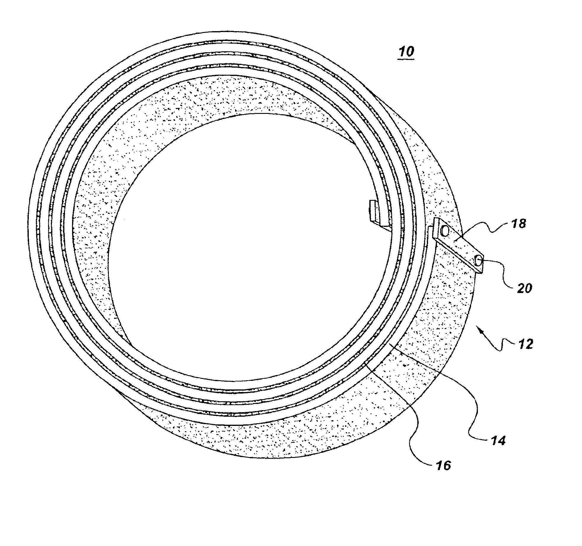
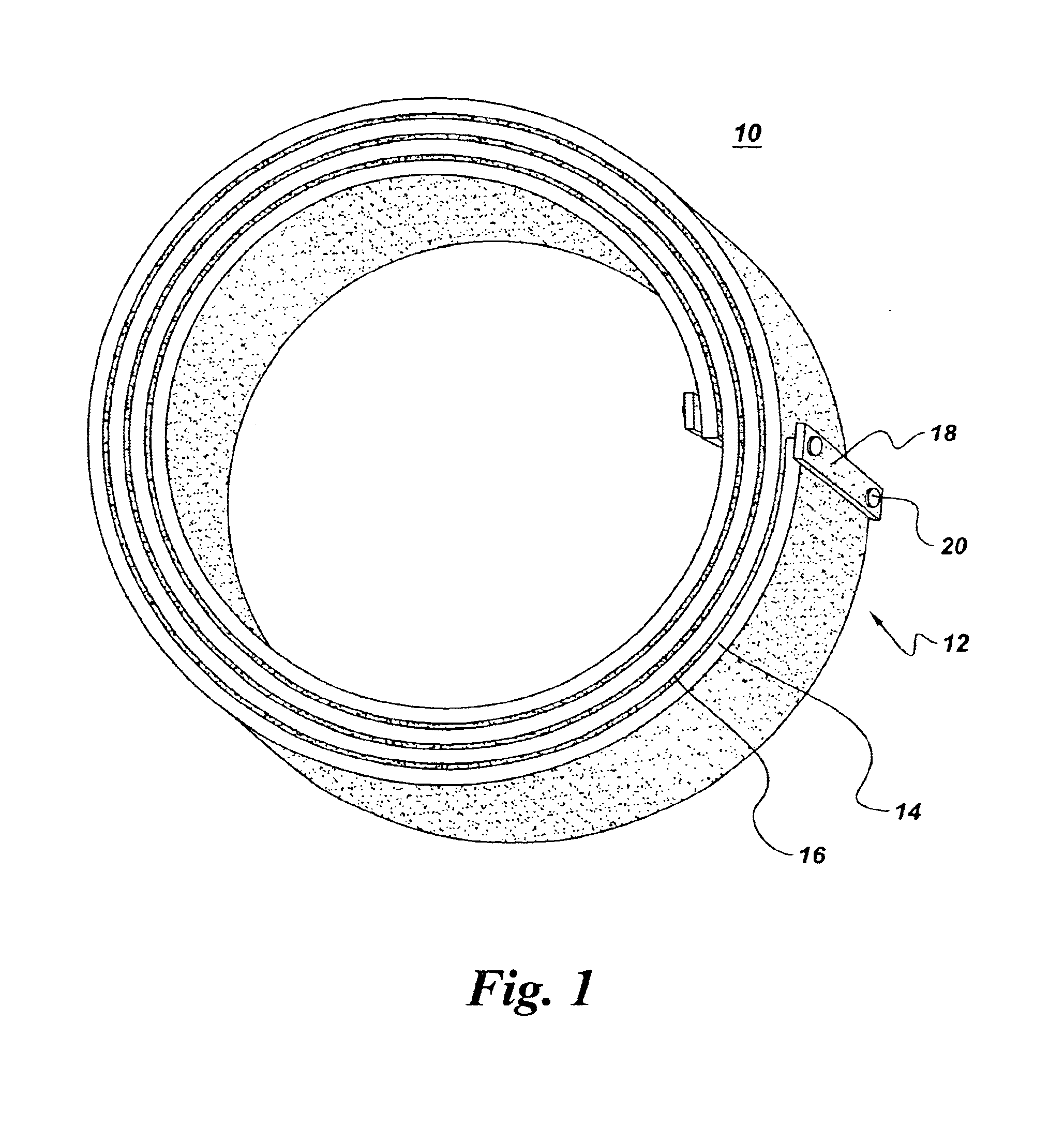
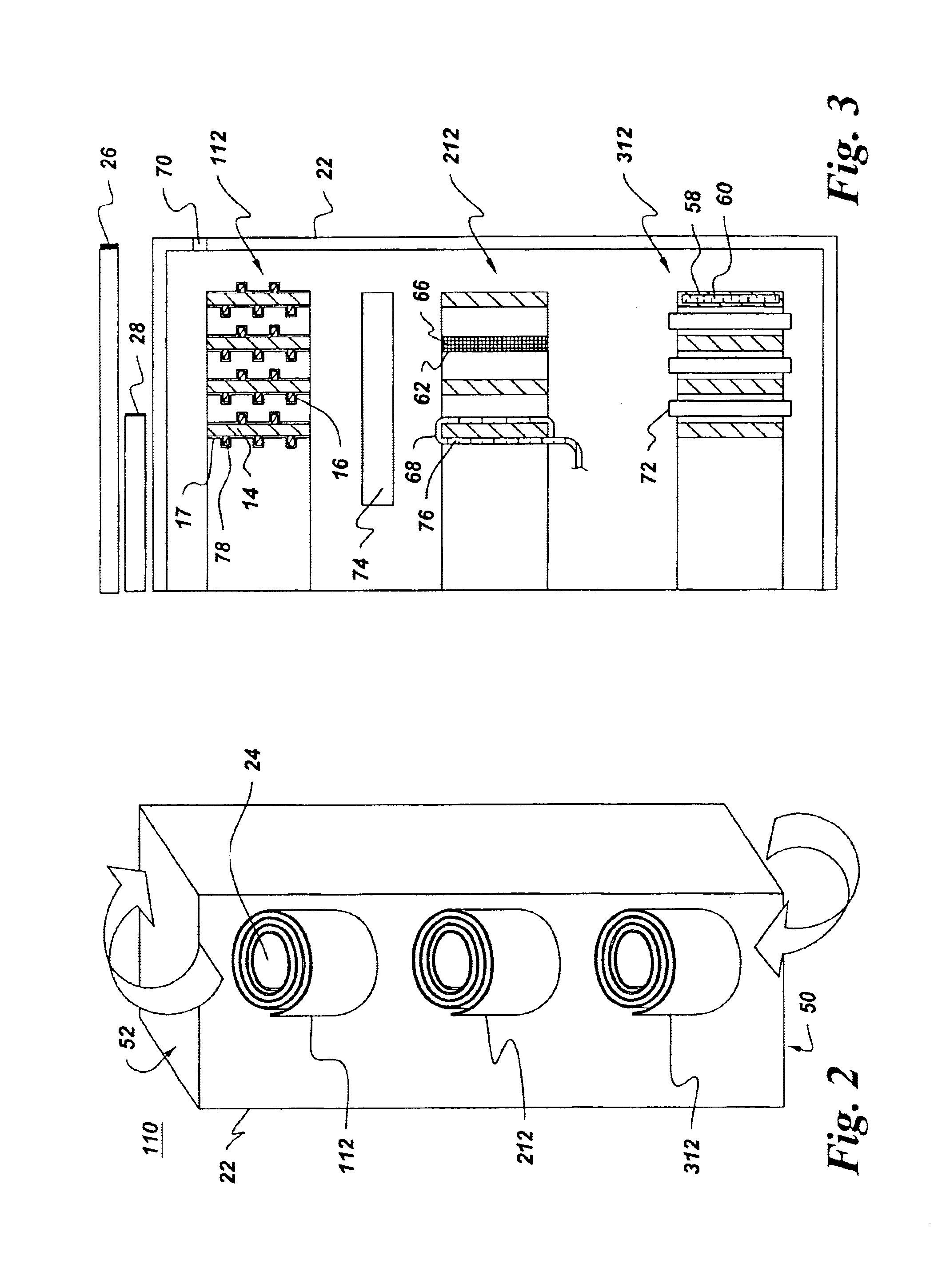
In one specific, non-limiting embodiment which is presented only for purposes of example with respect to a 600 volt, 5000 kA, 60 Hz system, a three-phase FCL is designed to be situated within an approximately 1 meter wide, 2.3 meter tall housing. To keep each phase of the FCL in the range of about 180 kilograms to about 230 kilograms, the spiral inductor is designed to comprise copper with a width of about 25.4 centimeters, a thickness ranging from about 10.16 millimeters to about 11.43 millimeters, an inner diameter of about 58 centimeters, an outer diameter of about 70 centimeters, and inter-turn spacing of about 16 millimeters. The predicted total three phase losses are calculated to be about 14.23 kilowatts (about 4.7 kW for the top inductor, about 4.83 kW for the middle inductor, and about 4.7 kW for the bottom inductor).

In the above example design, the desired inductance was predicted to be about 9.54 microhenries per phase. With such inductances, it is expected that a 600 vol...


PUM


Abstract

A fault current limiter (FCL) comprises: an air core flat clock spiral inductor comprising wound electrically conductive material and insulated turns; and two terminations configured for attaching the spiral inductor in series with a power carrying conductor.

Description

BACKGROUND OF INVENTIONThe invention relates generally to fault current limiting.When power is brought into a building, the components of the building's power system must be able to handle the possibility of a fault or sudden short circuit. In some systems, a fault can result in currents as high as 200 kA (kiloamps). Circuit breakers designed to withstand 200 kA short circuit currents are expensive.In one conventional technique for reducing fault current in an electric power system, for example, fused circuit breakers have been used. Fused circuit breakers have several limitations in that fused circuit breakers need to be manually reset, resulting in longer power outage times, and in that fused circuit breakers are expensive to buy as well as maintain.Another conventional technique includes a heavy current limiting busway which requires significant physical space. Still another conventional technique includes iron core reactors with cast-in-concrete construction. The current limitin...

Claims


Application Information

Patent Timeline
IPC IPC(8): H01F37/00H01F27/32H01F27/28
CPCH01F37/005H01F27/2823H01F27/322H01F27/2847
Inventor SHAH, MANOJ RAMPRASADPREMERLANI, WILLIAM JAMESIRWIN, PATRICIA CHAPMANGAO, GUANZHONGFROST, NANCY ELLENLAUSIER, KAREN BROADWELL
Owner GENERAL ELECTRIC CO
Why Eureka
Try Eureka