Method for measurement of pitch in metrology and imaging systems

a metrology and imaging system technology, applied in the field of metrology and imaging system measurement method, can solve the problems of noise in scan or other electronics, lack of accuracy, biased linewidth measurement, etc., and achieve the effect of reducing any noise in data

Inactive Publication Date: 2005-03-29
ASKARY FARID
View PDF6 Cites 43 Cited by
  • Summary
  • Abstract
  • Description
  • Claims
  • Application Information

AI Technical Summary

Benefits of technology

In another embodiment, the obtained data set is one or more image(s) of portions of a sample, and the one-dimensional profile data f(x) is obtained from the image(s) through one or more mathematical operations including operations on the obtained d...

Problems solved by technology

The features in a data set are rendered from features on the sample, though sometimes such data set features can result from noise in the scan or other electronics or from environmental factors such as vibration and other interferences.
However, metrology and imaging systems have imperfections consisting of, but not limited to, sharpness of excitation (probe sharpness), finite interaction volume of excitation and sample, detection limits and inefficiencies, finite depth of focus, signal to noise ratio limitations, diffraction, and image distortion.
With such metrology and imaging systems, the problem is in determining where the actual edge location lies along a complex waveform of the detected signal.
The net result of smearing and arbitrary edge assignment is that the linewidth measurement tends to be biased and suffers from lack of accuracy.
However, it is known in the prior art that all pitch measurement al...

Method used


Image

  • Method for measurement of pitch in metrology and imaging systems
  • Method for measurement of pitch in metrology and imaging systems
  • Method for measurement of pitch in metrology and imaging systems

Examples


Embodiment Construction

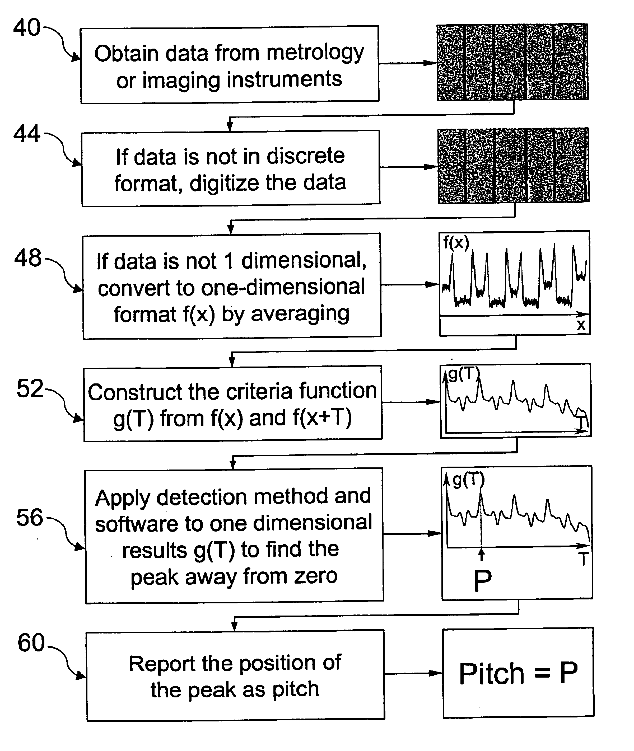
In accordance with an embodiment of the present invention, a method for measuring the pitch in any data set obtained from a metrology or imaging system is provided where such method does not rely on assigning edge locations, i.e., it does not involve application of edge detection algorithms. The method can be extended to data sets (images) in any number of dimensions. The data can be obtained from any imaging system such as cameras including CCD; optical microscopes; scanning electron microscopes including top down, tilt, and cross section; scanning probe microscopes including atomic force microscopes and profilometers; scanning ion microscopes; transmission electron microscopes; scanning optical microscopes; numerous other microscopes in analytical instruments, microscopes in lithography systems; defect detection and inspection microscopes whether optical or scanning electron; thermal imaging systems, medical imaging devices such as magnetic resonance imaging, CAT Scan; ultrasound ...


PUM


Abstract

In accordance with an embodiment of the invention, a method for measuring pitch in data obtained from metrology and imaging systems is provided. A data set from a metrology or imaging instrument is obtained. The data set is converted into digital format if not already in that format. The digitized data set is mapped into a one-dimensional profile data if the digitized data set is not already one-dimensional. The one-dimensional profile data denoted by f(x) is a function of x position values corresponding to equally spaced or nearly equally spaced pixels. A criteria function g(T) is constructed as a one-dimensional data array from the profile data f(x) or any of its derivatives and a translation of the profile data f(x) denote by f(x+T) or any of its derivatives. Here, T represents the amount of translation, and g(T) is a function of T translation values corresponding to equally spaced or nearly equally spaced pixels. A value of translation T is then determined either as a whole pixel or with subpixel interpolation such that the magnitude of g(T) would be either a maximum or a minimum whichever appropriate at said value, wherein the determined value is not zero. The determined value is then reported as the pitch in the data set.

Description

BACKGROUND OF THE INVENTIONPitch measurement is the measurement of the distance between two similar features. This definition applies to both the physical specimen and its image, that is, the corresponding data set collected from the specimen using a metrology or imaging system. The sample pitch is the spacing of similar elements in a specimen such as a grating. In most metrology and imaging systems, when a specimen with known sample pitch is measured or imaged, the spacing between similar features is rendered in the data set or image and the pitch in such data set or image can be used to determine the scale in the data set, for example, the magnification of the image. Thus, pitch measurement can be used for metrology or imaging system calibration to set the scale. If the scale is known in advance of data collection, a measurement of the sample pitch in a specimen with otherwise unknown pitch can be obtained from the pitch in the data set collected from the sample.Prior art methods ...

Claims


Application Information

Patent Timeline
IPC IPC(8): G06T7/00G01Q90/00G01Q60/00G06T7/40G06T7/60
CPCG06T7/40G06T7/602G06T2207/30164G06T2207/10061G06T7/62
Inventor ASKARY, FARID
Owner ASKARY FARID
Why Eureka
Try Eureka