Optical transmitter and optical transmission system using electro absorption modulator

Inactive Publication Date: 2005-03-29
LUMENTUM JAPAN INC
View PDF6 Cites 13 Cited by
  • Summary
  • Abstract
  • Description
  • Claims
  • Application Information

AI Technical Summary

Benefits of technology

Based upon the above, the aim of this invention is to provide the optical transmitter which has constant modulator output light and the highly reliable optical transmission system by using the optical transmitter.

Problems solved by technology

Due to chirping, the transmission degradation of the optical pulse occurs.
Generally, it is difficult to adjust the optical transmitter to achieve desired characteristic specifications since the fiber transmission characteristic and the optical transmitter output cannot be determined at the same time.
Also as one of the modulator output light is divided by the optical coupler 15, the loss of the modulator output for the transmission in the fiber becomes a substantial problem.
It is undesirable to set the optical coupler 15 for dividing the optical output, and the costs of and space for other optical parts are prohibitive.
For this reason, it is difficult to make an integrated EA / DFB optical source.

Method used


Image

  • Optical transmitter and optical transmission system using electro absorption modulator
  • Optical transmitter and optical transmission system using electro absorption modulator
  • Optical transmitter and optical transmission system using electro absorption modulator

Examples


Embodiment Construction

Hereafter the Embodiment example of this invention is explained by using the figures.

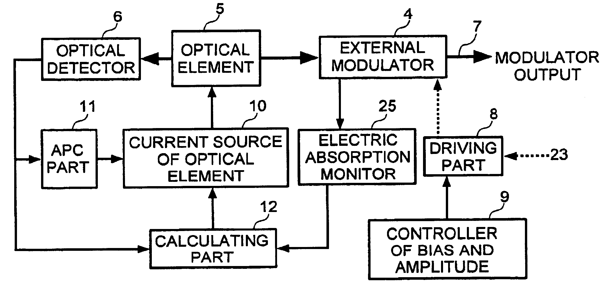
The best examplary embodiment of the optical transmitter according to the current invention is shown in FIG. 5 and includes an optical element 5, an optical element current source 10, an EA optical modulator 4 which modulates the front-face optical output of the optical element, a driving part 8 which drives the EA optical modulator 4 and receives an input data signal 23 to be transmitted, a bias and amplitude controller 9 which controls the bias voltage and the amplitude voltage of the driving part 8, an information delivery part 26 which transmits the information monitored the EA optical modulator and the driving part 8, a calculating part 12 which sets up the driving current of the optical element 5 using the changed value of the information delivery part 26, an optical detector 6 which monitors the back-face optical output of the optical element, and an APC part 11 which keeps the optical output...


PUM


Abstract

In the application of the optical transmitter to any system for the compensation of passing degradation, the invention provides the optical transmitter which maintains constant modulator output and the highly reliable optical transmission by tuning, the alpha parameter for given systems.As the optical element back-face output power detected by PD6 depends on the optical element driving current amount, the electronic absorption amount of the EA optical modulator monitored by the electronic absorption monitor depends on the optical output of the optical element 5 and the EA optical modulator driving point of the driving part 8. It is possible to detect a change in the driving point in the EA optical modulator by taking a difference between the amount monitored by the PD 6 and the amount monitored by the electronic absorption monitor. Consequently by applying to the driving current source 10 the current corresponding to the change of the EA optical modulator driving point, it is possible to automatically compensate the modulator output 7 when the driving point of the EA optical modulator changes due to the change of the alpha parameter and the passing degradation.

Description

BACKGROUND OF THE INVENTIONThis invention relates to the electric field absorption type or Electro Absorption (EA) optical modulator and the optical transmission system that applies to the optical transmitter which drives the Distributed Feed-Back (DFB) laser and the accumulated EA / DFB integration optical source.The development of optical transmitters for high-speed optical transmission has experienced tremendous growth in the information communication market in recent years. The fiber loss becomes the smallest to develop a relay distance if a laser beam is in the 1.5 μm band in the optical source or the optical element of the optical transmitters. However, the most of existing fibers are usual dispersion fibers which have the group velocity dispersion of 0 in the band light of 1.3 μm. For this reason, the group velocity distributing by the usual dispersion fibers is large in the band light of 1.5 μm.The large group velocity dispersion is caused by chirping that is one of the charac...

Claims


Application Information

Patent Timeline
IPC IPC(8): H04B10/155H04B10/152H01S5/50G02F1/015H04B10/07H04B10/40H04B10/50H04B10/516H04B10/564H04B10/58H04B10/60
CPCH04B10/505H04B10/50575H04B10/50572H04B10/5051
Inventor YAMAKI, KAZUYOSHISERIZAWA, HIDEYUKI
Owner LUMENTUM JAPAN INC
Why Eureka
Try Eureka