Multi-fiber catheter probe arrangement for tissue analysis or treatment

a multi-fiber catheter and probe technology, applied in the field of multi-fiber catheter probe arrangement for tissue analysis or treatment, can solve the problems of sensing and treating various tissue characteristics in the in vivo intravascular environment, and achieve the effect of reducing the diameter and spreading in the collection and/or delivery of energy

Inactive Publication Date: 2005-03-29
INFRAREDX INC
View PDF31 Cites 49 Cited by
  • Summary
  • Abstract
  • Description
  • Claims
  • Application Information

AI Technical Summary

Benefits of technology

Another further embodiment of the present invention contemplates the elongated generally cylindrically shaped probe having a proximal portion of reduced diameter, a central portion having a plurality of generally parallel spaced apart alignment grooves arranged peripherally therearound, and a distalmost nose portion. The distalmost nose portion preferably has a tapered forward end and a tapered rearward edge. The tapered rearward edge, of angular configuration, is a reflective surface. An arrangement of light-signal carrying fibers would be arranged within each of the alignment grooves. The signal fibers would have a distalmost face end through which light signals would be delivered and/or received by bouncing off of the reflective angular surface on the tapered rearward edge of the nose portion of the elongated housing. The nose cone of the elongated housing distal of the alignment grooves, may also be longitudinally displaceable with respect to the longitudinal axis of the elongated housing. A reflective surface may be somewhat arcuate or segmented in cross section or have angled reflective portions thereon to effect angular displacement of light energy signals being delivered or received from tissue adjacent to the elongated probe in the distal end of a catheter in which the tissue analysis/treatment is being undertaken.
A yet further

Problems solved by technology

The sensing and treating of various tissue characteristics in the in vivo intravascular environment is desirous fo

Method used


Image

  • Multi-fiber catheter probe arrangement for tissue analysis or treatment
  • Multi-fiber catheter probe arrangement for tissue analysis or treatment
  • Multi-fiber catheter probe arrangement for tissue analysis or treatment

Examples


Embodiment Construction

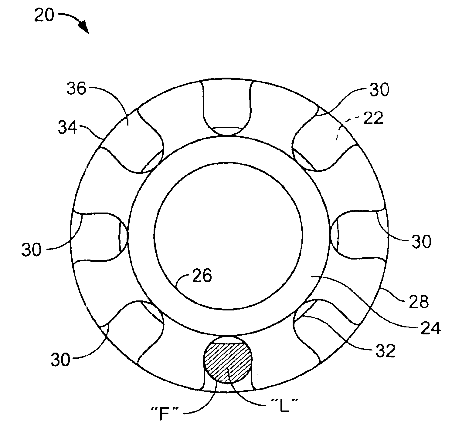
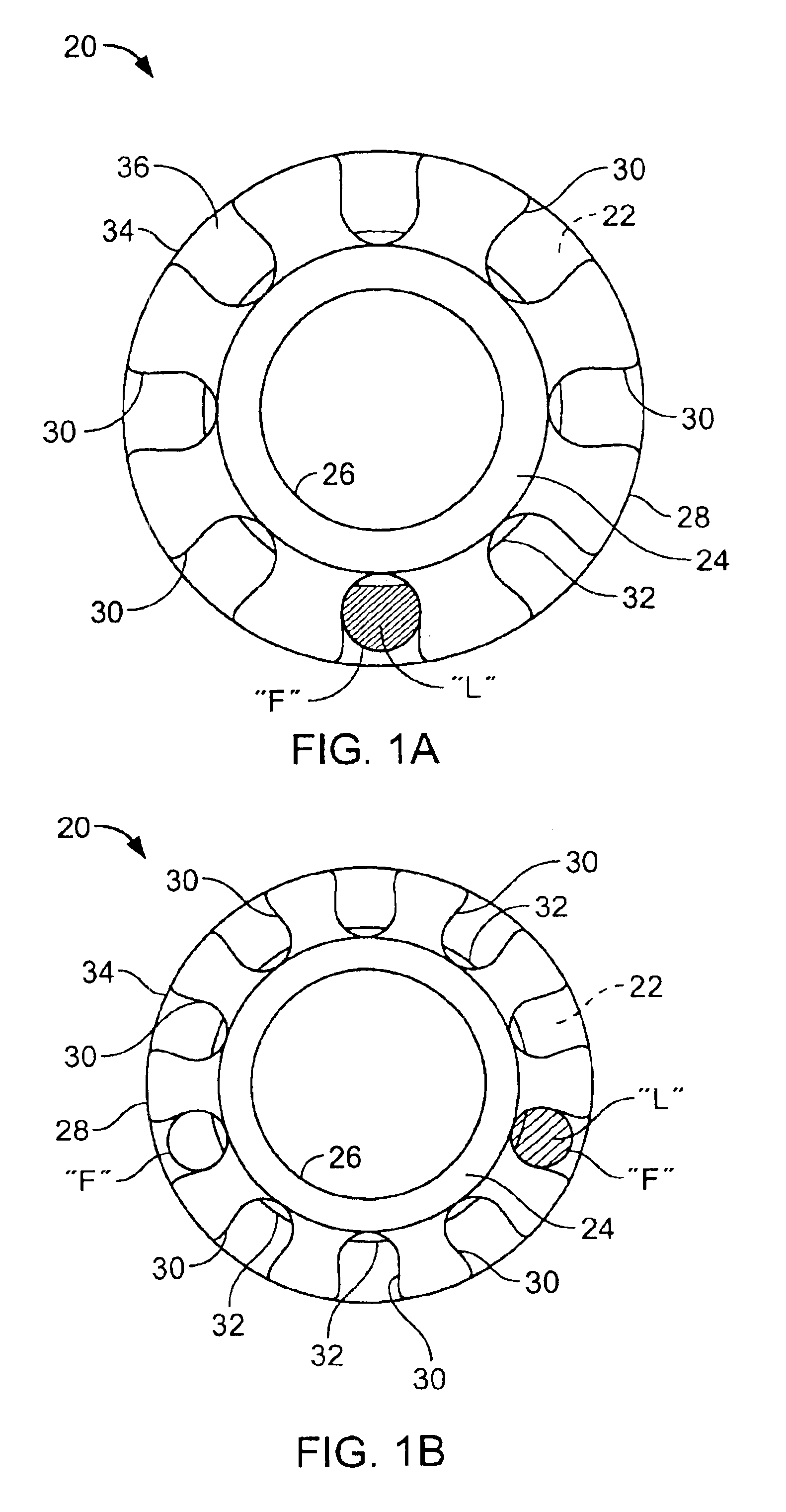
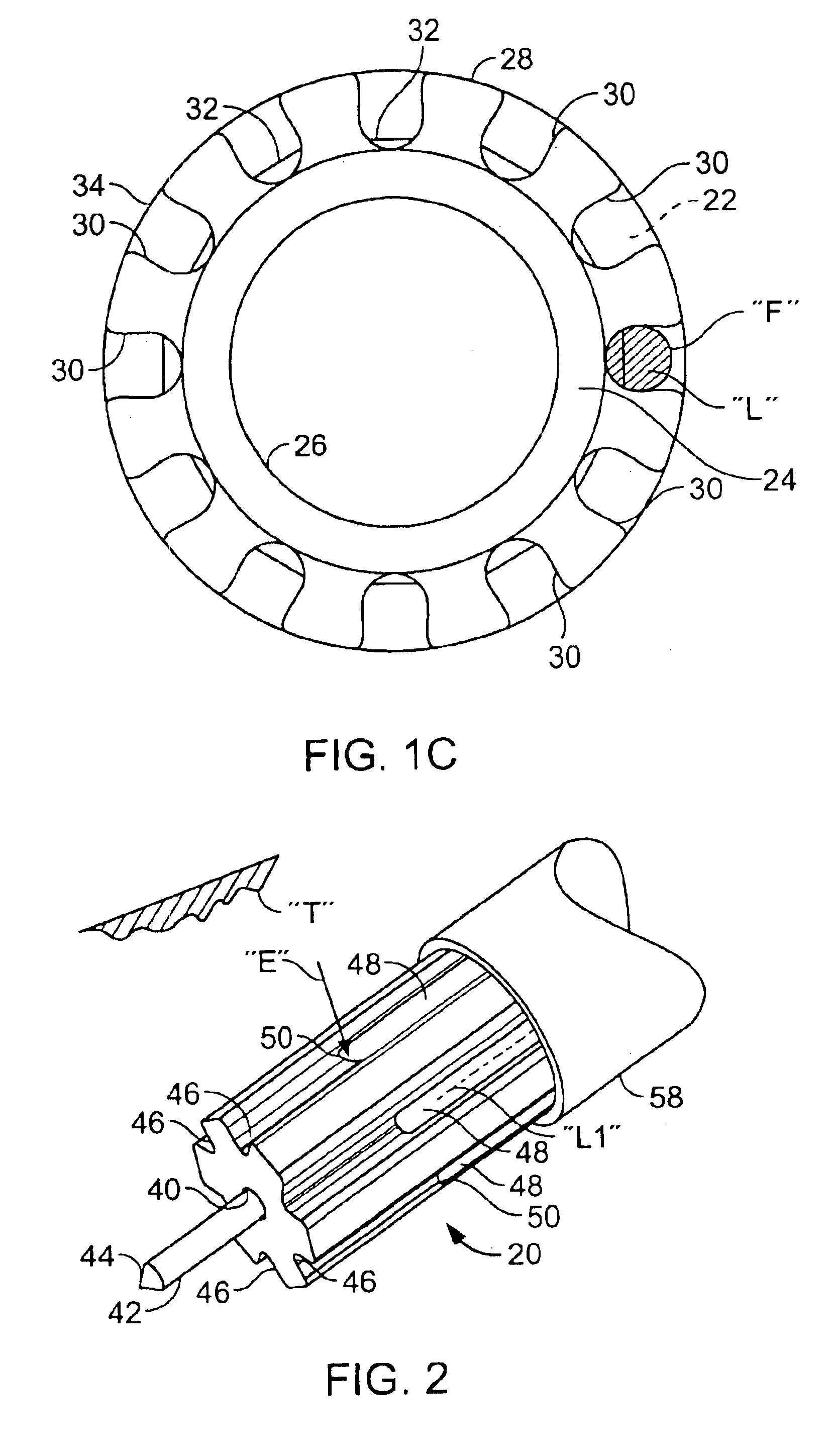
Referring now to the drawings in detail, and particularly to FIGS. 1(A), 1(B) and 1(C) there is shown in end views, the first preferred embodiments of the present invention which comprises an elongated generally cylindrically shaped housing 20 having a first or distal 22, and a second or proximal end 24. The housing 20 in a first preferred embodiments have a central bore 26 extending axially therethrough, which may be characterized as a lumen for receiving other elongated devices such as a guidewire or signal carrying members such as fibers or waveguides. The housing 20 has an outer peripheral surface 28 having a plurality of spaced apart, parallel, longitudinally directed alignment grooves 30 thereon, extending only axially along a central portion of the axial length of the housing 20. FIG. 1(A) discloses eight such grooves 30, FIG. 1(B) disclosing ten such grooves 30 and FIG. 1(C) disclosing twelve such fiber supporting grooves 30. A step-like ledge or shoulder 32 may be arranged ...


PUM


Abstract

A catheter tip apparatus is arranged in a catheter for the delivery and collection of an energy signal to permit analysis and/or treatment of body tissue by the energy signal. The apparatus comprises an elongated housing having a plurality of annularly disposed elongated grooves arranged thereon; and a flexible energy-bearing fiber arranged in each of the elongated grooves. Each of the fibers have a proximal end in communication with an energy delivery source or a signal analysis center. Each of the fibers also have a distalmost end in communication with a reflector for analysis and treatment of body tissue in which the catheter is disposed.

Description

BACKGROUND OF THE INVENTIONField of the InventionPrior ArtThe sensing and treating of various tissue characteristics in the in vivo intravascular environment is desirous for many reasons yet difficult because it is a very harsh environment in which to conduct such analysis or treatment. The presence of blood and its constituents such as cholesterol may effect scattering and absorption of energy signals transmitted within an organ. Diagnosis and treatment of various tissues within the human body using an in vivo probe necessitates adaptive characteristics for that probe when it is inserted into a mammalian body organ.It is an object of the present invention to provide a probe for insertion within a mammalian body which overcomes the disadvantages of the prior art.It is a further object of the present invention to provide a minimally invasive device for wave energy transmitting (i.e. photonic) diagnosis and treatment of mammalian tissue through the use of endoscopes, catheters and oth...

Claims


Application Information

Patent Timeline
IPC IPC(8): A61B18/20A61B18/24A61B1/06A61B1/07A61B18/22A61B5/00A61B17/00A61B1/313
CPCA61B1/00073A61B1/00096A61B1/0615A61B1/07A61B18/24A61B1/3137A61B2018/2272A61B2017/00057A61B2018/208A61B2018/2211A61B5/0084
Inventor FURNISH, SIMON M.
Owner INFRAREDX INC
Why Eureka
Try Eureka