Control embedded machine condition monitor

a condition monitor and embedded machine technology, applied in the direction of mechanical roughness/irregularity measurement, instruments, nuclear elements, etc., can solve the problems of over-simplification and inability to provide reliable, and over-complication of techniques at the upper range of the spectrum

Inactive Publication Date: 2005-03-29
WELLS FARGO BANK NAT ASSOC +1
View PDF3 Cites 8 Cited by
  • Summary
  • Abstract
  • Description
  • Claims
  • Application Information

AI Technical Summary

Benefits of technology

These and other needs are met by the present invention wherein analog signals generated in response to one or more operating parameters of a machine, such as, for example, vibration, temperature, sound, force, pressure, motor current or lubricant oil temperature, viscosity or composition, are converted into root-mean-square (“rms”) values which are periodically sampled, sorted into predefined rms value bands and stored as an evolving

Problems solved by technology

Techniques at the lower range of the monitoring and analysis spectrum are overly-simplified and do not provide reliable results whereas techniques at

Method used


Image

  • Control embedded machine condition monitor
  • Control embedded machine condition monitor
  • Control embedded machine condition monitor

Examples


Embodiment Construction

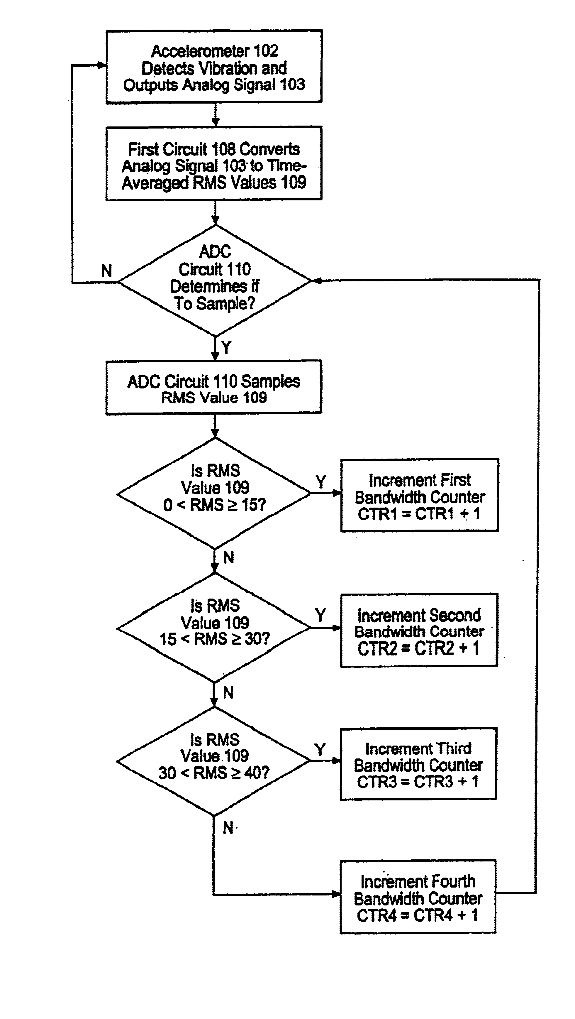
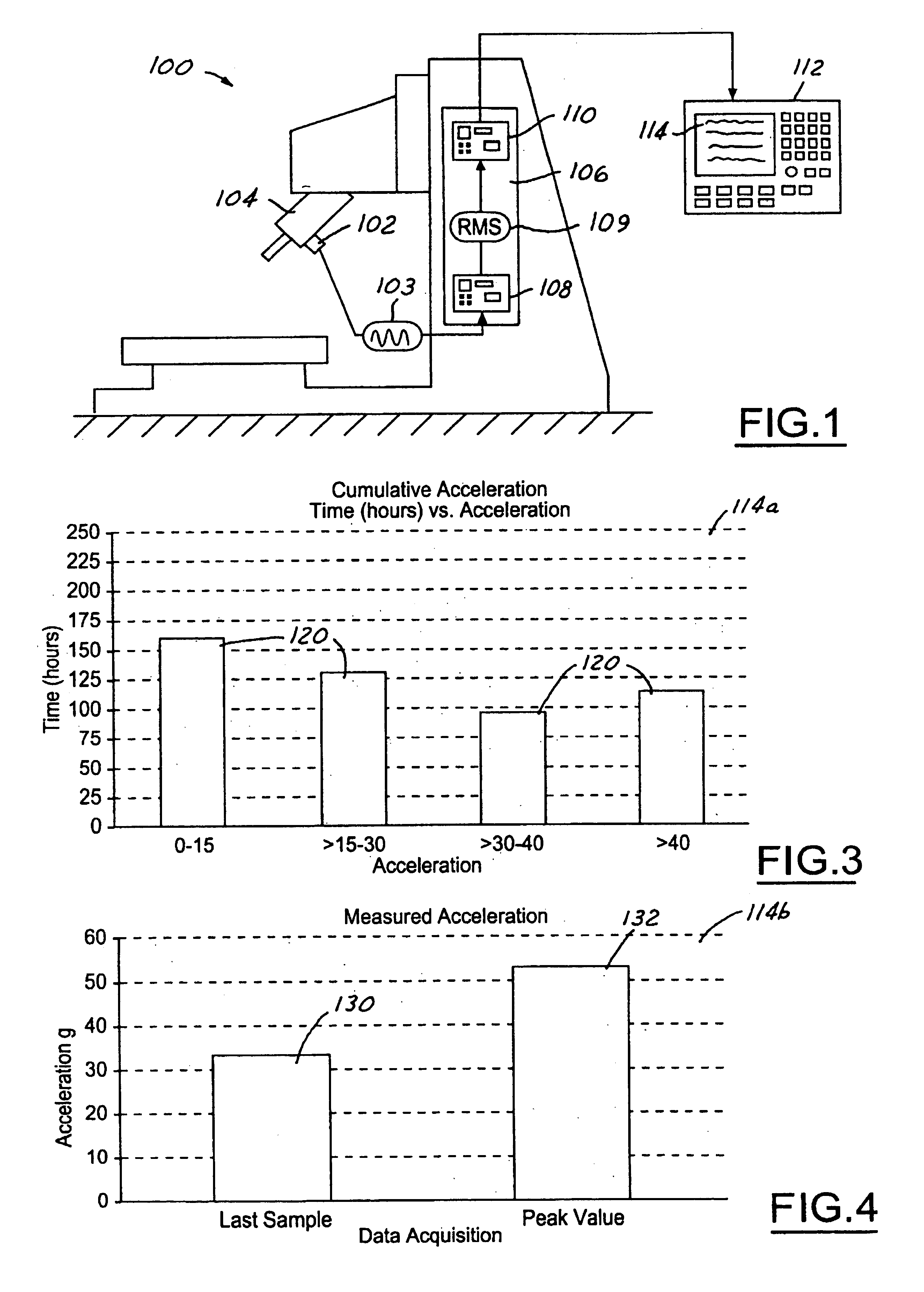
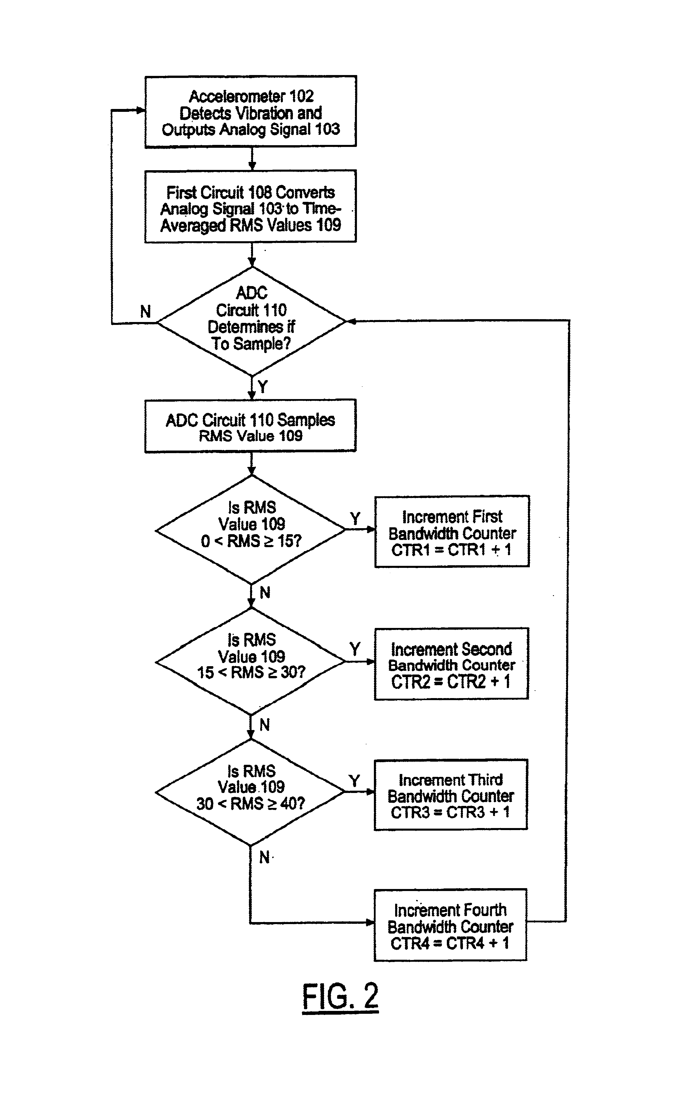
A preferred embodiment of the present invention will now be described with reference to the various drawing figures, wherein FIG. 1 is a schematic side view of an exemplary machine tool, such as, for example, a vertical machining center 100. It will be apparent to those of ordinary skill in the art, upon reading the within description, that the apparatus and method according to the various embodiments of the present invention may be practiced with respect to machines of alternative configurations, structures and operations without departing from either the spirit or the scope of the present invention. For example, the apparatus and method according to the various embodiments of the present invention may be used on any combination of other machine tools, such as horizontal machining centers, turning centers, milling machines, profilers, routers, planers, boring mills, drills, broaches, gear-cutters, screw-cutters, shapers, grinders, press brakes or reamers, on any combination of comp...


PUM


Abstract

Analog signals are generated in response to one or more operating parameters of a machine such as vibration and used to provide a log of the operating history of the machine. The analog signals are converted into root mean square (rms) values which are periodically sampled. The sampled signals are sorted into predefined rms value bands. Each occurrence of a signal in an rms value band is used to increment a counter in order to keep track of the number of occurrences of signals in a particular rms value band. The number of accumulated signals in each of the rms value bands provides an indication of the usage and condition of the machine.

Description

BACKGROUND OF THE INVENTIONThe present invention relates in general to methods and apparatus for monitoring the operation and use of a machine. More particularly, the present invention relates to methods and apparatus for monitoring the operation and use of a machine for the purpose of diagnosing the mechanical condition of the machine based thereon.It is known to monitor machine operation parameters, such as, for example, machine vibration, temperature, sound, force or pressure, motor current or lubricant oil temperature, viscosity or composition, and to evaluate such monitored parameters for the purpose of providing an indication of the condition of the machine. For example, a thermocouple may be located within the lubricant “bath” so as to alert the machine operator when the temperature of the oil has exceed some predetermined threshold value. In another example relating to machine vibration, techniques employed to monitor and to analyze machine vibration for the purpose of provi...

Claims


Application Information

Patent Timeline
IPC IPC(8): G01H1/00G07C3/00
CPCG01H1/00G07C3/00G01H1/003
Inventor CURLESS, RICHARD A.MCCALMONT, PAUL E.
Owner WELLS FARGO BANK NAT ASSOC
Why Eureka
Try Eureka